A design for manufacturing guide for engineers and sourcing teams to reduce tooling risk, control cost, improve quality, and scale production

A part can look finished in CAD and still fail the
first production review. Wall sections vary too much, draft is missing,
tolerances are tighter than the process can hold, and assembly depends on hand
fitting that will not survive volume. That is where a practical design for
manufacturing guide becomes valuable – not as a theory document, but as a way
to prevent delays, tooling rework, and avoidable cost before release.
For product teams, DFM is less about making a design
simpler in the abstract and more about aligning the design with a real process,
a real supplier, and a real target cost. A prototype can prove geometry. It
does not automatically prove manufacturability. The design choices that work in
CNC machining, SLA, or soft tooling may need adjustment before injection
molding, die casting, stamping, or full assembly.
What a design for manufacturing guide should actually
do
A useful design for manufacturing guide should help a
team answer four production questions early. Can the part be made consistently
with the intended process? Can it be inspected without creating a bottleneck?
Can it be assembled efficiently at the required volume? And can all of that
happen at a commercial cost that still supports the product margin?
If a guide only covers geometric rules without
connecting them to tooling, quality, and throughput, it is incomplete. Most
production issues happen at the interfaces between design, tooling, process
capability, and assembly planning. A housing may mold correctly but warp after
ultrasonic welding. A stamped bracket may meet dimensional targets but create
fixture issues downstream. A silicone keypad may function well but show
cosmetic variation that the approval standard did not clearly define.
That is why DFM should be reviewed as part geometry,
part process selection, and part production planning.
Start with process selection before finalizing the
design
Many avoidable redesigns happen because teams lock the
CAD too early. The correct sequence is usually to define performance
requirements, estimate annual volume, identify likely manufacturing processes,
and then tune the design around those constraints.
The same part may be technically possible in several
ways, but not equally suitable. CNC machining gives speed and precision for
prototypes and lower volumes, but unit cost can become unfavorable at scale.
Injection molding reduces piece price at higher volumes, but it introduces
tooling investment, draft requirements, gate location concerns, and stricter
rules around wall thickness and shrinkage. Die casting works well for many
metal housings and structural parts, but porosity, tooling layout, and
post-machining requirements need to be considered from the start.
This is where trade-offs matter. A design optimized
for cosmetic appearance may need added ribs that create sink risk. A part
optimized for strength may require thicker sections that increase cycle time. A
design optimized for low tooling cost may create more labor during assembly.
There is no universal best solution. The right answer depends on volume,
tolerance, finish, and how the product is built as a whole.
Design for manufacturing guide for plastic parts
Plastic components are often where DFM has the biggest
impact because small design decisions directly affect mold complexity, cycle
time, appearance, and scrap rate.
Wall thickness should be consistent where possible.
Large thickness transitions tend to create sink, voids, and uneven cooling. If
extra stiffness is needed, ribs are usually better than simply adding bulk, but
rib proportions still need control. Oversized ribs can print through to the
visible surface or create local packing issues.

Draft is another common problem. A vertical wall that
looks fine on screen may stick in the mold or require expensive side actions if
the release direction was not considered. Even when a part can technically
eject with minimal draft, the cosmetic result may suffer, especially on
textured surfaces.

Parting line location matters more than many teams
expect. It affects appearance, flash risk, and mold construction. The same
applies to gates and ejector pins. If cosmetic surfaces, logos, and assembly
features are not prioritized early, the tooling stage becomes an exercise in
compromise.

Color masterbatch and dispersant levels also directly
influence flow marks. Even with consistent wall thickness, improper additive ratios can create
visible flow lines on cosmetic surfaces. If the dispersant is insufficient, the
color masterbatch fails to blend evenly with the base resin during injection,
leaving streak-like flow marks. Conversely, overusing dispersants may alter
melt viscosity, causing hesitation marks at the gate or weld lines. During DFM,
we always evaluate the material's additive package — balancing masterbatch
concentration and dispersant flow is critical to avoid cosmetic rejects.

Tolerance strategy should also reflect molding
reality. Tight tolerances across multiple plastic components can create low
yield and unnecessary inspection effort. In many cases, functional datums and
selective tolerance tightening are better than applying an aggressive general
tolerance across the entire part.
Below are three common tolerance reference tables.
These are not meant to be memorized — they are cited directly on your drawing
block. Simply write the standard code (e.g. ISO 2768-mor ISO 20457 TG6 W/NW) in
the title block, then assign individual tolerances only to critical features
like bearing holes, snap-fits, and locating posts. Non-functional surfaces and
cosmetic ribs do not need ±0.05. Defining this during DFM saves far more time
than arguing over CMM reports later.
Table 1: General Tolerances for Machined Parts — ISO
2768-1 (selected)
|
Nominal Dimension (mm) |
f (fine) ±mm |
m (medium) ±mm |
c (coarse) ±mm |
|
0.5–3 |
0.05 |
0.10 |
0.20 |
|
3–6 |
0.05 |
0.10 |
0.30 |
|
6–30 |
0.10 |
0.20 |
0.50 |
|
30–120 |
0.15 |
0.30 |
0.80 |
|
120–400 |
0.20 |
0.50 |
1.20 |
Source: ISO 2768-1 General tolerances — Part 1:
Tolerances for linear and angular dimensions without individual tolerance
indications. Writing ISO 2768-min the drawing block means all untoleranced
dimensions follow the medium class.
Table 2: Tolerances for Injection Molded Parts — ISO
20457:2018 (TG6 standard grade, selected)
|
Nominal Dimension (mm) |
W (tool-related) ±mm |
NW (non-tool-related) ±mm |
|
1–3 |
0.07 |
0.12 |
|
10–18 |
0.22 |
0.26 |
|
18–30 |
0.26 |
0.31 |
|
30–50 |
0.31 |
0.37 |
|
50–80 |
0.37 |
0.57 |
Source: ISO 20457:2018 Plastics moulded parts —
Tolerances and acceptance conditions. TG1 is the tightest, TG9 the loosest. W =
tool-specific dimensions; NW = non-tool-specific. Note: the 2018 edition has
been superseded by the 2026 edition, but the 2018 version remains widely used
in industry drawing blocks.
Table 3: German Standard for Plastics — DIN 16901
(Material Group 130, e.g. ABS, PC, PC+ABS)
|
Nominal Dimension (mm) |
A (non-tool-determined) ±mm |
B (tool-determined) ±mm |
|
0–1 |
0.18 |
0.08 |
|
6–10 |
0.20 |
0.10 |
|
30–40 |
0.27 |
0.17 |
|
70–90 |
0.44 |
0.34 |
|
120–160 |
0.60 |
0.50 |
Source: DIN 16901 Plastics moulded parts — Tolerances.
A = dimensions affected by moving tool components, wall thickness variations,
or ejector pin interaction; B = dimensions formed directly within the same mold
half. For new projects, ISO 20457 is recommended, but many European customer
BOMs still reference DIN 16901.
Metal parts need a different DFM logic
Metal parts often get overconstrained because teams
carry machining assumptions into stamping or die casting programs. Each process
has its own design rules, and forcing one process to behave like another
usually increases cost.
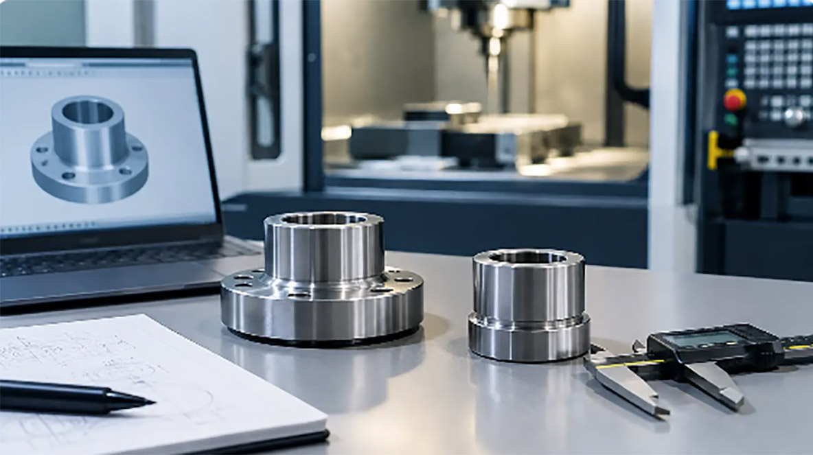
For machined parts, DFM often means reducing
unnecessary setups, avoiding deep narrow features that require special tooling,
standardizing thread sizes, and keeping tolerances tight only where function
requires it. Internal corners should match practical cutter sizes. Surface
finish callouts should be selective. A part that is fully machinable can still
be commercially inefficient if it demands excessive tool changes or long cycle
times.
For stamped parts, bend radii, material springback,
grain direction, hole-to-edge distance, and progressive die feasibility should
be considered early. A bracket may look simple in flat pattern form but become
unstable in production if the bend sequence is poorly chosen.
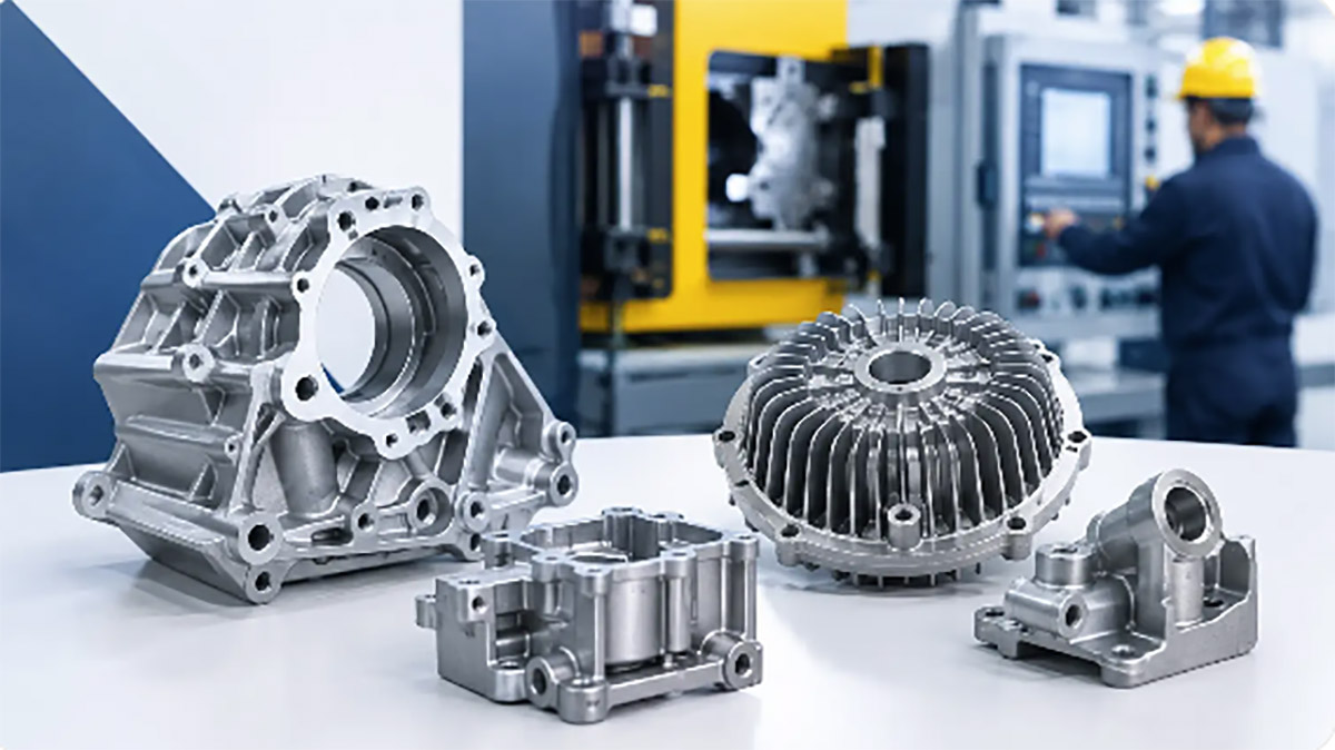
For die cast components, wall uniformity, flow path,
draft, and post-machining allowances need to be defined with the casting
process in mind. Designers sometimes specify cosmetic or dimensional requirements
that are better achieved through secondary machining or localized process
control rather than pushing the casting beyond a reasonable capability window.
Process Selection Quick Reference Table
The same part can often be made by multiple processes,
but cost and lead time vary significantly. This table helps you narrow down the
direction during DFM review.
|
Process |
Best suited for |
Avoid when |
Key DFM constraints |
|
CNC machining |
Prototypes, low volume (<500 pcs), high
precision, complex geometry |
High volume (unit cost doesn't drop) |
Avoid deep narrow cavities, match internal corner
radius to cutter size, minimize setup changes |
|
Injection molding |
High volume (>1,000 pcs), consistent quality
required |
Low volume (tooling amortization too high) |
Uniform wall thickness, draft angle ≥1°, avoid sharp
corners, consider sink and weld lines |
|
Sheet metal stamping |
High volume, thin-walled parts, brackets and
enclosures |
Thick plates (>6 mm), complex 3D curved surfaces |
Min bend radius ≥ material thickness, hole edge
distance ≥ 2x thickness, account for springback |
|
Die casting |
High volume metal parts, heat sinks, structural
housings |
Low volume, extremely high density requirements |
Uniform wall thickness, avoid sharp corners, leave
machining allowance, account for porosity |
DFM is also assembly design
A product can have well-designed individual parts and
still be expensive to build. That is why a good design for manufacturing guide
should include assembly from the beginning, not after the part files are
released.
Fastener count is an obvious example. Reducing screw
quantity can save more than hardware cost. It can shorten assembly time, reduce
torque verification points, and simplify service procedures. But replacing
screws with snaps is not automatically better. Snap fits may reduce labor, yet
they can introduce mold complexity, stress concerns, or difficult rework during
pilot builds. The right choice depends on product life, repair needs, cosmetic
sensitivity, and the expected assembly environment.
Part orientation, poka-yoke features, cable routing,
adhesive cure time, and fixture access all affect throughput. If a part can be
installed in the wrong direction, eventually it will be. If a connector is
difficult to reach, assembly time will drift. If a cosmetic surface must
contact a fixture during bonding, yield may suffer even when the design is
dimensionally correct.
Teams that review DFA together with DFM usually catch
these problems earlier and avoid treating assembly issues as shop-floor
exceptions.
Quality planning belongs in the DFM review
Manufacturability is not only about whether a part can
be made. It is also about whether it can be measured and controlled repeatably.
Critical dimensions should be linked to function, not
just copied from the CAD model. Cosmetic standards should be defined by zone
and acceptance level. Material specifications should match real supply options.
If a component requires special jigs, leak testing, go-no-go gauges, or CMM inspection, those requirements should be known before production launch.
This is particularly important when a product moves
from prototype to tooling. Prototype methods can hide variation. CNC and SLA
parts often arrive with a level of attention and manual finishing that cannot
represent normal mass production conditions. If the approval standard is based
on prototype quality without considering process capability, the first
production run may trigger avoidable disputes over fit, finish, or appearance.
A disciplined DFM review should ask what the likely
failure modes are, how they will be detected, and whether the control plan is
realistic at the planned volume.
Case: DFM flags a risk → Prototype validates → Then
mass production
We saw a case where DFM flagged a potential weld line
issue at a boss junction on a PC+ABS housing. The draft angle was within spec,
the wall thickness was uniform, but flow simulation suggested the knit line
would fall exactly at a load-bearing point. Rather than assuming the fix, we
cut a rapid prototype tool, shot 50 parts, and tested the boss under torque.
The weld line held within specification, so no design change was needed — but
without the prototype validation, the team would have either overcorrected the
design or risked a steel mold correction later.

How to use this design for manufacturing guide in a
real project
The best time for DFM is before tooling kickoff, but
after the product requirements are stable enough to evaluate trade-offs.
Earlier is better if the production process is already known.
In practice, the review should include design,
manufacturing, sourcing, and quality input. The goal is not to turn every
conversation into a redesign loop. The goal is to flag the few issues that
drive most of the risk: process mismatch, unnecessary tolerance burden,
avoidable tooling complexity, assembly inefficiency, and weak inspection
strategy.
For teams working across multiple part types, it is
often more effective to review by manufacturing family. Plastic molded parts,
machined metal components, silicone parts, cosmetic housings, and final
assembly each carry different risks. Separating those discussions usually
produces clearer decisions than trying to resolve everything in a single
general meeting.
A capable manufacturing partner can shorten this step
by linking prototype learning, tooling considerations, and production feedback
under one workflow. That is especially useful when a program includes mixed
processes such as CNC prototypes, plastic tooling, silicone components, sourced
hardware, and final assembly. Xiamen Creator Technology typically supports
these transitions by reviewing manufacturability in relation to the actual
build path rather than treating each process in isolation.
DFM Review Quick Checklist — 7 questions to run
through before tooling kickoff:
- Is wall thickness uniform? Is the ratio between thickest and thinnest
section within 2:1?
- Do all vertical faces have sufficient draft? Has draft been increased
for textured surfaces?
- Are tolerances separated into functional and non-functional
categories? Is the standard referenced in the drawing block?
- Does the parting line and gate location avoid the primary cosmetic
surface?
- Are poka-yoke features included for assembly? Are there any
hard-to-reach screw positions or connectors?
- Are critical dimensions linked to a measurement method and inspection
fixture plan?
- If DFM raised a risk item, is there a prototype validation plan in
place before steel tooling?
Good DFM does not make products generic. It makes them
producible, measurable, and economically viable. If a design review forces a
few hard choices early, that is usually a sign the process is working. It is
far less expensive to change a model than to correct a mold, retrain an
assembly line, or explain a delayed launch after production has already
started.
FAQ
- What is a design for manufacturing guide used for? It helps engineering and
sourcing teams identify manufacturability risks before tooling commitment,
covering geometry, process selection, tolerance strategy, assembly, and
quality planning.
- How does DFM reduce injection molding tooling cost? By catching issues like
uneven wall thickness, inadequate draft, and overly tight tolerances
early, DFM reduces the likelihood of steel modifications, rework, and
delayed delivery.
- What tolerance standard is commonly used for plastic molded parts? ISO 20457 and DIN 16901
are the two most common standards. ISO 2768-1 is typically used for
machined parts.
- When should prototype validation happen before mass production? Whenever DFM identifies
a risk that cannot be confirmed through simulation alone — such as weld
line strength, snap-fit durability, or cosmetic finish under production
conditions.
- What causes flow marks in injection molding? Common causes include
insufficient melt temperature, slow injection speed, and — as covered in
this guide — improper masterbatch or dispersant ratios that affect
material flow consistency.