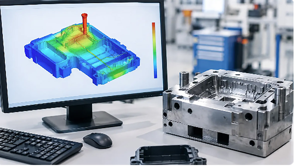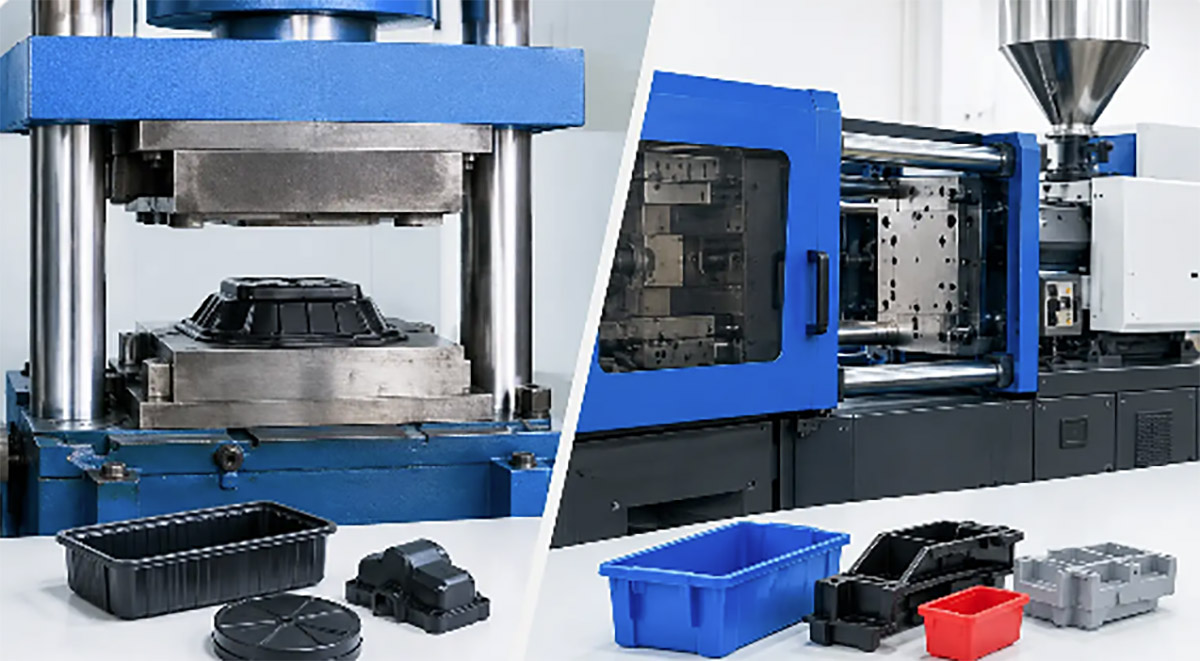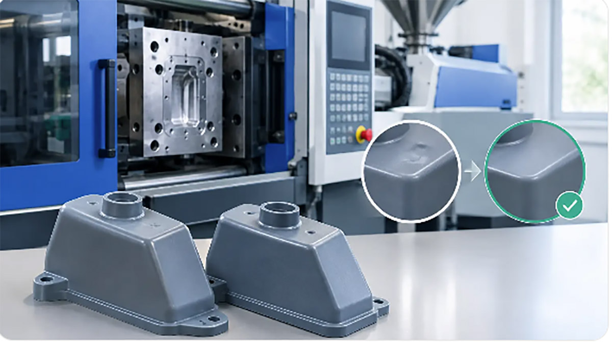
Learn how to prepare files for CNC machining with practical checks for geometry, tolerances, materials, threads, and inspection requirements before quoting

A
CNC quote can look straightforward until a machinist opens the model and finds
an undefined thread, a tolerance applied to every surface, or a pocket that no
standard cutter can reach. Knowing how to prepare files for CNC machining helps
prevent these issues before they become quote delays, engineering questions, or
costly revisions on the shop floor.
For product teams, the
objective is not merely to send a CAD file. It is to provide a controlled
manufacturing package that tells the supplier what the part must do, which
requirements are critical, and where there is room to select an efficient
process. A clear package supports faster DFM review, more reliable pricing, and
fewer assumptions during prototype or production machining.
Start With a Clean, Native CAD
Model
The 3D model is the foundation of the CNC machining
package. Submit a native CAD file when possible, along with a neutral format
such as STEP. Native files preserve feature history and can make it easier for
the manufacturing engineer to evaluate edits, while STEP files provide a
dependable exchange format across CAD platforms.
Before release, check that the
model contains one finished solid body per part unless the assembly
intentionally includes multiple bonded or separately machined components.
Remove hidden construction geometry, duplicate bodies, obsolete configurations,
and imported surfaces that do not form a watertight solid. A model that appears
correct on screen may still contain gaps, overlapping surfaces, or
zero-thickness features that cause CAM errors.
Use the model to define the
final part geometry, not an idealized concept that will be corrected later in a
drawing. Hole depths, fillets, chamfers, draft features, counterbores, and
pockets should be modeled accurately. If a feature is not represented in the
model but is essential to function, call it out clearly in the drawing.
For assemblies, provide an
assembly file or a simple exploded view when mating relationships affect
machining decisions. This is particularly useful for enclosure halves,
fixtures, housings, and components with alignment pins, press-fit inserts, or
post-machining assembly operations.
Use a 2D Drawing to Control
Critical Requirements
A STEP file defines shape, but it rarely communicates
the complete manufacturing intent. A dimensioned PDF drawing remains essential
when the part has tolerances, thread specifications, finish requirements, datum
references, or inspection needs.
The drawing should identify
the part number, revision, material, quantity, units, and general tolerance
standard. It should also include only the dimensions needed to fully define the
part. Avoid duplicating dimensions from multiple views unless they serve a
clear inspection purpose. Conflicting dimensions create uncertainty, even when
the differences are small.
Apply tolerances according to
function. A bearing bore, sealing face, locating feature, or mating interface
may require a tighter tolerance than the rest of the component. By contrast,
cosmetic exterior surfaces and non-mating profiles often allow broader
tolerances. Tightening every dimension by default can significantly increase
machining time, inspection effort, scrap risk, and unit cost.
Where position and orientation
matter, use datums and GD&T rather than relying on a chain of plus-or-minus
dimensions. For example, the position of a mounting-hole pattern is normally
more meaningful when controlled relative to the surfaces that locate the part
in the final assembly. This gives the machinist a practical inspection
reference and protects the feature that matters most.
Design Features That CNC Tools Can
Actually Reach
CNC machining is flexible, but cutters have physical
limits. A file should be reviewed with tooling access in mind before it is
released for quotation.
Internal corners are a common
issue. Standard end mills are round, so inside pocket corners will retain a
radius. If a mating square component must sit fully into a pocket, add
appropriate corner relief, such as dog-bone relief, or revise the mating
geometry. Do not specify sharp internal corners unless a secondary process such
as EDM is acceptable for the application and budget.
Deep, narrow pockets and small
holes deserve extra attention. As cutter length increases relative to diameter,
tool deflection, chatter, cycle time, and breakage risk increase. A deep cavity
may still be feasible, but it can require specialized tooling or multiple
operations. If the feature is not functionally necessary, a wider pocket,
reduced depth, or larger corner radius can improve manufacturability.
Also review undercuts and side
features. Some can be machined with specialty tools, multiple setups, or 5-axis
equipment. Others may require redesign. It depends on the orientation, required
finish, tolerance, and expected production volume. A clear note about whether a
feature is functional, cosmetic, or optional helps the supplier propose the
right trade-off.
Specify Material, Condition, and
Surface Finish
Material selection should be more specific than simply
stating aluminum, steel, or plastic. Identify the alloy or grade, temper or
condition where relevant, and any material standard required by your
application. Aluminum 6061-T6 and 7075-T6, for example, differ in strength,
corrosion behavior, cost, and machining response. Stainless steel grades can
vary substantially in corrosion resistance and machinability.
If the part will be heat
treated, plated, anodized, painted, bead blasted, or powder coated, state this
in the drawing and quote request. Surface treatments can change dimensions,
surface appearance, conductivity, corrosion resistance, and fit. A
close-tolerance hole that receives coating may need masking, post-processing,
or a revised tolerance strategy.
Define cosmetic expectations
with enough detail to be evaluated. A note such as “natural anodized finish” is
not always sufficient if color consistency, scratch direction, masking
boundaries, or visible tool marks matter. Identify cosmetic surfaces and
non-cosmetic surfaces separately. For a customer-facing housing, photographs,
color references, or approved sample standards can prevent subjective
disagreements later.
Surface roughness should be
called out only where it affects performance or appearance. Sealing surfaces,
sliding interfaces, optical components, and certain adhesive surfaces may
require a defined roughness value. Applying a fine finish requirement to every
surface adds cost without improving the part’s function.
Define Holes, Threads, and Hardware
Interfaces Clearly
Holes are among the most frequently misunderstood
features in a CNC package. Identify whether each hole is through, blind,
drilled, reamed, tapped, counterbored, countersunk, or intended for a threaded
insert. For blind holes, specify the usable thread depth rather than assuming
the full drilled depth can be threaded.
Thread callouts should state
the standard, nominal size, pitch where applicable, class if required, and
depth. Include whether the thread must be formed before or after surface
treatment. For metric threads, use complete metric callouts rather than mixing unit
systems in the same drawing.
When the part uses PEM
hardware, helicoils, heat-set inserts, dowel pins, bearings, or press-fit
components, provide the hardware part number or exact installation requirement.
The receiving hole may need a tolerance that differs from the nominal hardware
catalog recommendation, particularly after anodizing, plating, or
molding-related assembly operations.
Include Inspection Priorities and
Revision Control
Not every dimension needs the same inspection method.
If your part has a few high-risk characteristics, identify them. These may
include a critical bore diameter, flatness of a sealing face, concentricity
between turned features, or distance between an electrical connector and
mounting points.
For prototypes, a standard dimensional
report may be sufficient. For production parts, you may require first articleinspection, material certificates, coating certificates, gauge
records, or sampling plans. State these requirements early because they
influence process planning and cost.
Revision control is equally
important. Each released file should use the same part number and revision
identifier across the CAD model, drawing, bill of materials, and purchase documentation.
Do not send several files with names such as “final,” “final2,” or “latest.” A
single controlled release folder reduces the risk of machining an outdated
version.
Build a Complete CNC Machining RFQ
Package
A supplier can quote more accurately when the
engineering files are accompanied by commercial and production context. Include
annual volume or expected lot size, prototype quantity, target delivery date,
and whether the order is a one-time build or the beginning of a repeat program.
For complex projects, the RFQ
package should include the following:
·
Native CAD and STEP files for each part
·
Dimensioned PDF drawings with revision control
·
Material, finish, and hardware specifications
·
Assembly information or critical mating-part details
·
Required quality documents and inspection expectations
·
Quantity breaks and forecast volume
·
A list of critical functional or cosmetic requirements
This information allows the
manufacturing team to recommend suitable machining approaches, identify
features that may require redesign, and determine whether additional processes
such as injection molding, die casting, stamping, or assembly may be more
economical at higher volumes.
Treat DFM Feedback as Part of File
Preparation
Even well-prepared files benefit from a manufacturing
review. The most useful DFM feedback does not simply identify problems. It
compares options: maintain the design with added machining cost, alter a
feature for standard tooling, split a part into two components, or change the
process as volume increases.
For example, a CNC-machinedaluminum prototype may be the right choice for early
validation, while a molded or die-cast version becomes more practical after the
design and demand stabilize. Preparing accurate CNC files at the prototype
stage makes those later production decisions easier because the functional
dimensions, material requirements, and assembly interfaces are already
documented.
Xiamen Creator Technology can
review CAD models, drawings, and manufacturing requirements before production
planning, helping teams identify practical changes without losing sight of
functional intent. The earlier questions are resolved, the more predictable the
quote, schedule, and finished-part quality will be.
A release package should give the machinist confidence, not force them to guess. When geometry, tolerances, materials, finishes, and inspection priorities are clear, CNC machining becomes a controlled production step rather than an extended cycle of clarification emails