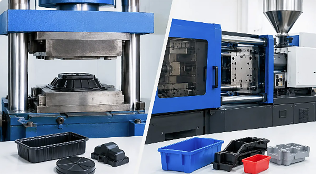
Mold flow analysis predicts how resin fills, packs, cools, and warps in a mold, helping teams prevent tooling changes, delays, and avoidable cost up front

A
steel mold can be machined exactly to the drawing and still produce parts with
short shots, sink marks, weld lines, flash, or unacceptable warpage. The issue
is often not machining quality. It is how the selected resin moves, packs,
cools, and shrinks inside the cavity. Mold flow analysis gives product teams
and toolmakers a practical way to identify those risks before steel is cut.
For companies moving from
prototype parts to injection molding, this analysis is not a substitute for
sound part design or experienced toolmaking. It is a decision tool. It helps
determine whether the proposed geometry, gate location, wall thickness,
material, and process window are likely to support stable production.
What Mold Flow Analysis Evaluates
Mold flow analysis uses simulation software to model
the injection molding cycle. A digital part model is combined with material
data and proposed molding conditions. The software predicts how molten plastic
enters the cavity, reaches the end of fill, packs under pressure, cools, and
contracts after ejection.
The value is not simply a
color plot showing resin movement. The useful output is a set of manufacturing
questions: Will the cavity fill before the material freezes? Where will
pressure peak? Can air escape from the last areas to fill? Will a cosmetic
surface show a weld line? Is the gate large enough to pack a thick section
before it freezes? Which features are most likely to distort after cooling?
A complete study commonly
reviews fill pattern, fill time, injection pressure, clamp force, shear rate,
melt-front temperature, weld lines, air traps, cooling behavior, volumetric
shrinkage, and warpage. For complex tools, the analysis may also compare runner
systems, valve-gate sequencing, conformal cooling concepts, or multi-cavity
balance.
Why Analysis Should Happen Before
Tool Release
Tool modifications are possible, but they are rarely
simple. Moving a gate may require changing the runner layout, cavity inserts,
cooling channels, ejector placement, and cosmetic surface treatment. Correcting
a warpage problem can involve a revised part design, an altered steel
condition, a material change, or all three.
Mold flow analysis is most
effective while the design still has room to change. At that point, increasing
a rib radius, adjusting nominal wall thickness, relocating a gate, or adding a
vent may take hours of engineering work rather than weeks of tool rework.
This matters especially for
programs with tight launch dates or multiple dependent components. A late
molding issue can delay painting, overmolding, assembly fixtures, electronics
integration, packaging validation, and pilot production. Finding risk early
protects more than the tooling budget.
Analysis also supports better
commercial decisions. A part may be moldable with a single cavity, for example,
but simulations can show whether the required cycle time or injection pressure
makes that approach inefficient at forecast volume. The best technical option
is not always the lowest-cost mold, and the lowest initial tooling price is not
always the lowest production cost.
Inputs That Determine Whether
Results Are Useful
Simulation quality depends on the assumptions behind
it. A study based on incomplete geometry or an approximate material grade can
point a team in the right direction, but it should not be treated as final
production evidence.
The most useful analysis
starts with a production-intent 3D model, including ribs, bosses, snap
features, texture-sensitive surfaces, inserts, and expected assembly
interfaces. The exact resin grade matters because two materials in the same
family can have different flow behavior, shrinkage, filler content, and
recommended processing ranges. Glass-filled nylon, flame-retardant PC/ABS,
polypropylene, and silicone each create different tooling and processing
considerations.
The team should also define
the likely molding approach. That includes the planned number of cavities, gate
type, gate position, runner system, machine limits, surface requirements, and
expected annual volume. A preliminary simulation can be run before every detail
is settled, but conclusions should be refined as the mold concept becomes more
defined.
Four inputs deserve particular
attention:
·
Wall thickness and transitions: Thick-to-thin changes influence flow, packing,
cooling time, and sink risk.
·
Material selection: Viscosity, filler orientation, shrinkage, and moisture sensitivity
affect both simulation and production behavior.
·
Gate strategy: Gate size and location determine flow length, pressure demand,
weld-line placement, and pack efficiency.
·
Cooling concept: Cooling is often the largest contributor to cycle time and can
strongly affect warpage.
Common Problems Mold Flow Analysis
Can Expose
Short-shot risk is one of the
clearest findings. If a long, thin flow path reaches a restrictive feature near
the end of fill, the melt may freeze before the cavity is complete. The
solution might be a larger gate, a different gate
location, a
revised wall section, a higher-flow material, or a more capable molding
machine. Each option has trade-offs in part appearance, cycle time, tooling
cost, and material performance.
Weld lines require more
judgment. They occur where separate melt fronts meet, such as around holes,
openings, or multiple gates. Some weld lines are acceptable on noncritical
areas. Others can reduce strength or create visible lines on a customer-facing
surface. Analysis helps locate them, but the design team must decide which
locations are functionally and cosmetically acceptable.
Air traps are another frequent
concern. When air cannot vent from the last areas to fill, it can cause
burning, incomplete fill, or unstable processing. Simulation identifies likely
trapped-air locations so vents, ejector venting, parting-line changes, or gate
changes can be considered before the tool design is fixed.
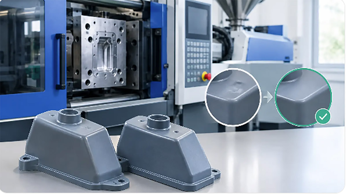
Sink marks and voids are
generally tied to thick features that cannot pack or cool uniformly. A heavy
boss at the back of a cosmetic panel is a typical example. The practical
correction may be coring the boss, reducing its diameter, changing its
connection to the main wall, or revising the gate to improve packing. Simply
increasing hold pressure can mask the issue while creating flash or excessive
stress elsewhere.
Warpage is often the most
difficult result to interpret. It can be driven by uneven cooling, nonuniform
shrinkage, molecular orientation, fiber orientation, or geometry that lacks
stiffness. A simulation may predict a direction of distortion accurately, but
the final amount can still vary with machine setup, actual resin lot, moisture
control, tool temperature, and process consistency. Warpage results should
guide engineering decisions, then be verified through first-article
trials and
measurement.
Turning Results Into Tooling
Decisions
A useful mold flow review does not end with a report.
It ends with documented actions. The part designer, tooling engineer, and
manufacturing team should review the findings together because each group sees
a different constraint.
For example, moving a gate
away from a cosmetic face may improve appearance but place the vestige on an
assembly surface. Adding material to reduce warpage may increase weight and
cycle time. A hot runner can improve material efficiency and gate control, but
it adds tool complexity and maintenance requirements. There is no universal
simulation setting that resolves these decisions automatically.
The strongest approach is to
rank issues by production impact. A predicted short shot, excessive injection
pressure, or severe warpage usually requires action before tooling release. A
weld line in a hidden, low-stress area may be acceptable. This prevents teams
from spending time optimizing minor plot variations while missing a problem
that could stop production.
When changes are made,
rerunning the analysis is usually worthwhile. Comparing the original and
revised design creates a record of why a gate moved, why a rib was adjusted, or
why the material choice changed. That record supports tooling approval and
helps troubleshoot later if trial results differ from the simulation.
What Analysis Cannot Replace
Mold flow analysis reduces
uncertainty, but it does not eliminate the need for DFM
review, mold
design review, resin supplier guidance, and disciplined process development.
Software cannot confirm that a draft angle is adequate for a textured surface,
that a thin shutoff will survive high-volume cycling, or that an assembly will
tolerate normal part variation without proper engineering input.
It also cannot compensate for
poor execution after tooling begins. Tool steel selection, machining accuracy,
vent maintenance, cooling line construction, resin drying, machine capability,
and inspection standards all affect the finished part. A well-modeled part
still needs a controlled mold trial and a clear path for correcting issues
found during sampling.
For product teams, the
practical question is not whether every injection molded part needs the same
level of simulation. A simple, thick-walled part with generous tolerances may
only need a focused fill and gate review. A thin-wall enclosure, glass-filled
structural component, high-gloss consumer surface, or multi-cavity production
tool generally justifies a deeper study. The higher the cost of a late change,
the more valuable early analysis becomes.
Xiamen Creator Technology can incorporate
mold flow findings into DFM, tooling development, sampling, and production
planning, keeping design decisions connected to the process that will make the
final part. The most useful result is not a simulation report by itself. It is
a tool design that reaches stable production with fewer corrections,
predictable quality, and fewer surprises at the press.