Learn how to prepare manufacturing drawings that reduce quoting delays, clarify tolerances, and support reliable tooling, production, inspection, and assembly at every stage.

A
part can look inexpensive in a 3D model and become expensive on the shop floor
because one critical requirement was never defined. Knowing how to prepare
manufacturing drawings turns design intent into instructions that a machinist,
mold maker, quality inspector, and assembly team can execute consistently. For
outsourced production, the drawing is also the reference that keeps quoting,
tooling, inspection, and supplier communication aligned.
A manufacturing drawing does
not need to describe every feature with maximum precision. It needs to define
the features that matter, identify acceptable variation, and remove assumptions
before production starts. The right level of detail depends on the process,
annual volume, material, and functional risk of the part.
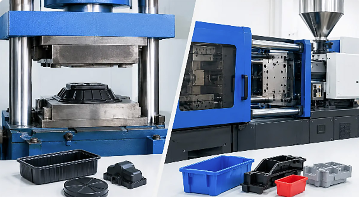
Start With the Production Process
The same geometry requires different drawing decisions
when it is CNC machined, injection molded, die cast, stamped, or cast in
silicone. Before dimensioning a part, confirm how it is expected to be made.
This avoids specifications that are technically possible but commercially
impractical.
For a CNC-machined enclosure, hole positions, thread
callouts, surface finish, and datum relationships may be the main concerns. For
an injection-molded housing, wall thickness, draft, gate
location considerations, parting-line tolerance, shrinkage, and cosmetic
surfaces need earlier attention. A stamped metal bracket may depend on bend
radii, grain direction, burr direction, and flat-pattern dimensions.
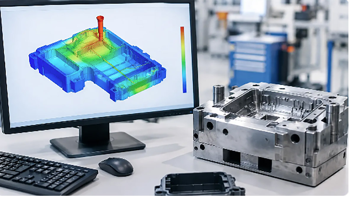
This is where design for
manufacturability review has practical value. A supplier can identify whether a
tight tolerance requires a secondary operation, whether an undercut needs a
side action in a mold, or whether a cosmetic surface will be affected by
ejector-pin placement. Resolve these issues before releasing drawings for
tooling or production, not after samples reveal them.
Build a Clear Drawing Package
A production-ready package normally includes a 3D CAD
model and a 2D drawing. The model communicates overall form efficiently, while
the drawing establishes controlled requirements for manufacturing and
inspection. Do not assume a supplier will extract all necessary dimensions from
the model. A model without clear tolerances, revision control, or inspection
criteria leaves too much room for interpretation.
Use a Consistent Title Block
The title block should identify the part number, part
name, material, finish, drawing revision, scale, units, and release date.
Include the company or project identifier when multiple products may be active
with the same manufacturer.
Revision control is
particularly important during prototype-to-production transitions. If a hole
diameter changes from a prototype version, the new revision must be visible in
the drawing, file name, and change record. A supplier should never have to
guess whether an attached CAD file supersedes a previously approved version.
Choose Views That Show Intent
Use enough orthographic views, sections, and detail
views to make every functional feature understandable. Hidden lines can help,
but a section view is usually clearer for internal pockets, wall thicknesses,
counterbores, ribs, and stepped bores.
Dimension features from
logical reference surfaces rather than chaining dimensions across the part.
Chained dimensions accumulate variation and can make inspection inconsistent.
If two mounting holes must align with a mating component, locate them from
shared datums, not from a sequence of intermediate edges.
Add detail views for small
features that could be misread at the primary drawing scale. This is useful for
snap fits, thin lips, retaining grooves, engraved marks, small radii, and
edge-break requirements.
Define Datums and Tolerances Around
Function
A tolerance should reflect how the part works, not
simply what is easy to place on a drawing. Start by identifying the surfaces
that locate the part in assembly. These often become primary, secondary, and
tertiary datums.
For example, a machined
mounting plate may use its bottom face as datum A, one side face as datum B,
and an adjacent side as datum C. Hole position can then be controlled relative
to these three references. The inspection approach matches the assembly
approach, which reduces disagreement between the design team and supplier.
Avoid applying tight
tolerances to every dimension. Over-tolerancing increases machining time,
inspection effort, scrap risk, and tooling cost without necessarily improving product
performance. General tolerances can cover noncritical dimensions, while
critical interfaces receive specific requirements.
Geometric dimensioning and
tolerancing can be valuable for parts with precise mating relationships,
rotating components, sealing surfaces, or complex inspection needs. However,
GD&T should be used only when the design team and manufacturing partner can
apply and inspect it correctly. A simple plus-or-minus tolerance may be the
better choice for a low-risk prototype or a noncritical feature.
Consider the process
capability. A tolerance that is reasonable for a precision CNC operation may be
unrealistic for as-molded plastic, die casting, or sheet metal forming. Plastic
materials also change with temperature, moisture, and time. When a dimension is
critical on a molded part, specify the measurement condition and discuss
expected shrinkage before the tool is cut.
Specify Material, Finish, and
Cosmetic Requirements
Material descriptions must be specific enough to
source and verify. Rather than writing only “aluminum” or “plastic,” identify
the grade or resin family, color where relevant, flame rating, reinforcement,
and any required compliance standard. If equivalent materials are acceptable,
state the permitted alternatives and the approval process.
Surface finish requirements
deserve the same discipline. For machined parts, identify a roughness value
only where it serves a function, such as a sealing face or sliding surface. For
molded components, distinguish between textured, polished, painted, and
non-cosmetic areas. For metal parts, define the finish system, color, thickness
or standard where applicable, and whether masking is needed on threads, contact
pads, or grounding locations.
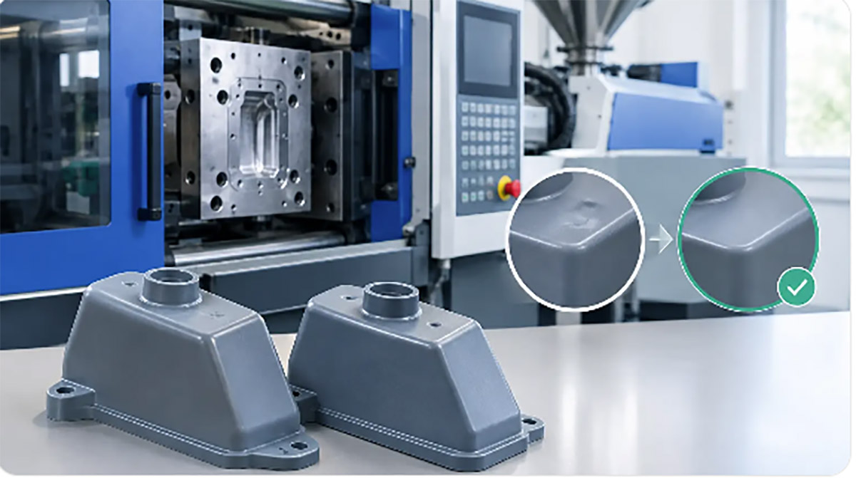
Cosmetic expectations are
often missed because they are difficult to express with a single dimension. Use
notes to identify the visible side, acceptable gate vestige location, allowed
witness lines, permissible color variation, and limits for scratches, sink
marks, flow lines, or flash. A physical approved sample can be useful for
appearance standards, but the drawing should still state the basic acceptance
criteria.
Add Manufacturing Notes Without
Repeating the Model
Notes should clarify requirements that cannot be
communicated clearly through dimensions alone. They should not become a
collection of generic statements copied from an old drawing.
Useful notes may define
deburring, edge breaks, thread standards, laser marking content, cleanliness,
packaging orientation, or special inspection requirements. For example, “Remove
all burrs and break sharp edges 0.2 mm maximum” gives a machinist a workable
instruction. “Parts must be high quality” does not.
Be careful with blanket
requirements such as “no defects” or “all dimensions critical.” Those
statements are not measurable and can create disputes during incoming
inspection. Define the defect, the location, and the allowable condition
instead.
Assembly drawings may need
additional information beyond the individual part drawings. Show fastener type
and torque, adhesive location and cure requirement, cable routing, polarity,
label placement, and the sequence for installing fragile or constrained
components. For an OEM product build, a clear bill of materials and approved
component list are as important as the geometry.
Make Inspection Possible
Every critical requirement should have a realistic
method of verification. Ask how a supplier will measure it before final
release. A deep internal diameter may require a bore gauge. A molded part
profile may need a checking fixture or CMM. A color or texture requirement may
require a visual standard under defined lighting.
Call out critical-to-function
features explicitly, but limit them to dimensions that genuinely affect fit,
safety, sealing, performance, or regulatory compliance. If all dimensions are
marked critical, none receive meaningful priority during process control.
For first article inspection,
establish the expected report format and sampling basis early. This is
especially helpful when a prototype becomes a repeat production part, when
tooling is transferred, or when several suppliers produce related components.
Inspection records should reference the same revision as the released drawing.
Run a Release Check Before Sending
Files
Before requesting quotations or releasing production
files, confirm that the package answers the questions a manufacturer will ask:
·
Does the 3D model match the current 2D drawing revision?
·
Are units, material, finish, and process assumptions clearly stated?
·
Are critical dimensions tied to functional datums and achievable
tolerances?
·
Are cosmetic, assembly, marking, and packaging requirements defined where
needed?
·
Can each critical feature be inspected with a practical method?
This check prevents a common
source of delay: a quote based on incomplete information followed by
engineering changes once the supplier begins DFM review. Early clarification
may add a day to drawing preparation, but it can prevent weeks of tooling
rework or repeated sample iterations.
When to Involve a Manufacturing
Partner
Bring a manufacturing partner into the drawing review
when the part involves multiple processes, uncertain tolerances, custom
tooling, or a transition from prototype to volume production. A prototype may
be machined from solid material, while the production version is injection
molded or die cast. The functional requirements can remain the same, but the
drawing must evolve to reflect the production process.
Xiamen Creator Technology can
support this transition with drawing review, DFM feedback, prototyping,
tooling, production, assembly, and quality coordination under one workflow. The
most useful supplier feedback is specific: which tolerance drives cost, which
feature creates tooling risk, and what revision would improve repeatability
without compromising function.
A manufacturing drawing is not
finished when every dimension is present. It is finished when the production
team can make, inspect, and assemble the part without relying on assumptions.
That standard creates faster quotations, cleaner approvals, and a more
predictable path from CAD data to finished product.