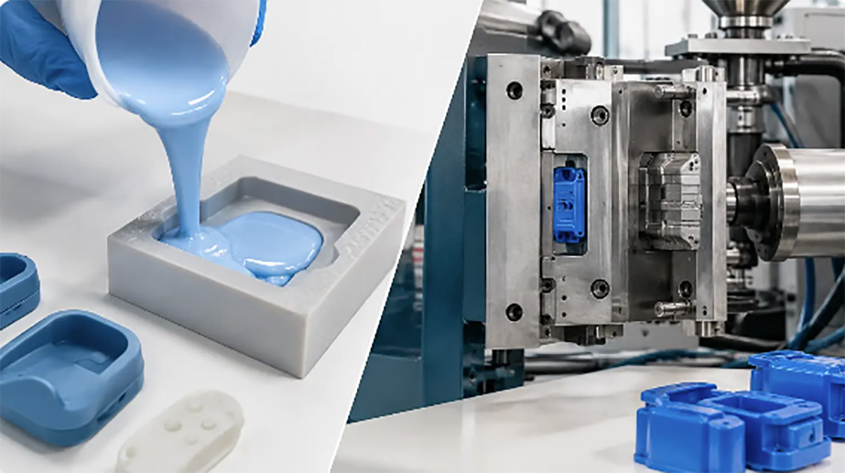
Identify injection molding warpage causes, connect defects to design, tooling, material, and processing choices, and reduce distortion in production runs.

A
part can leave the mold looking acceptable, then distort enough during cooling
to miss a fixture, rock on a flat surface, or create an assembly gap. Injection
molding warpage causes are rarely isolated to one machine setting. They usually
result from uneven shrinkage across the part, driven by a combination of part
geometry, material behavior, mold temperature, gate location, and packing
conditions.
For product teams, the
practical objective is not simply to make a warped part flatter after molding.
The objective is to identify where shrinkage becomes unbalanced and correct it
at the lowest-cost point in the process. A design adjustment during DFM is
generally less expensive than changing steel after tooling is complete. When a
tool is already in production, disciplined process trials can separate a material
or molding issue from a tooling limitation.
What Causes Warpage in Injection
Molding?
Warpage occurs when different areas of a molded part
shrink at different rates or in different directions. All thermoplastics shrink
as they cool. The problem begins when one section cools, packs, or orients
differently from another section, creating internal stress that pulls the
finished component out of its intended shape.
A thin, flat cover may bow
because its center remains hotter than its perimeter. A reinforced housing may
twist because glass fibers align differently on opposite sides of the flow
path. A long component with ribs may bend because the ribs shrink more than the
nominal wall. The visible defect may be a bow, twist, curl, or a localized
sink-related deformation, but the underlying mechanism is differential
shrinkage.
Uneven Wall Thickness
Non-uniform walls are among the most common injection
molding warpage causes. Thick sections hold heat longer and continue shrinking
after thinner areas have already become rigid. This difference creates stress
through the part as it cools.
A gradual wall transition is
usually manageable. Abrupt changes are more likely to produce distortion, sink
marks, and longer cycle times. Ribs, bosses, corner reinforcements, and mounting
features need particular attention because they often create localized heavy
sections without appearing problematic in a basic CAD view.
As a design guideline, ribs
should normally be thinner than the nominal wall rather than equal to it. The
exact ratio depends on resin and cosmetic requirements, but reducing rib
thickness helps limit differential cooling while maintaining useful stiffness.
Where a thick functional area cannot be avoided, coring it out or redesigning
the load path may be more effective than trying to compensate with process
settings.
Mold Temperature Imbalance
Mold cooling must remove heat consistently from both
sides of the cavity and across the entire part. If one mold half runs hotter
than the other, the warmer side generally shrinks later and may pull the part
toward that side. Uneven cooling circuits, restricted water flow, poor circuit
placement, scale buildup, or inconsistent coolant temperature can all create
this condition.
This is especially significant
for large, flat parts, long covers, cosmetic panels, and components with broad
unsupported surfaces. A minor mold-temperature difference can create a
measurable flatness issue when the part spans a long distance.
Checking actual coolant inlet
and outlet temperatures, flow rates, and mold surface temperatures provides
more useful information than relying only on the temperature controller
setpoint. If warpage changes from cavity to cavity in a multi-cavity tool,
cooling balance and cavity-specific steel conditions should be investigated
before making broad machine adjustments.
Incorrect Gate Location or Gate
Size
The gate determines how molten resin enters, fills,
packs, and orients inside the cavity. A poorly located gate can create uneven
flow lengths, unbalanced pressure distribution, weld lines, and directional
stress. These effects become visible as warpage after ejection.
For example, center-gating a
symmetrical round part may support balanced filling, while edge-gating a large
flat panel can lead to different packing conditions at the near and far ends. A
gate that freezes too early may prevent sufficient packing in remote areas.
Conversely, an oversized gate can leave excessive stress near the gate region
or extend the time needed to reach stable shrinkage.
Gate selection is a trade-off.
The location that best controls warpage may not be ideal for gate vestige,
cosmetic appearance, automated degating, or downstream assembly. Mold-flow
analysis and prototype trials are useful when the part has tight flatness
requirements, asymmetrical geometry, or reinforced resin.
Inadequate Packing and Holding
Control
Packing pressure compensates for material shrinkage
while the gate remains open. If holding pressure is too low, too short, or
inconsistent, areas farther from the gate may receive insufficient material.
They then shrink more during cooling, increasing the risk of warpage and sink.
Increasing packing pressure is
not automatically the right answer. Excessive pressure can overpack the gate
area, increase residual stress, create flash, or make ejection more difficult.
The correct approach is to establish the gate-freeze time, then set holding
pressure and time to achieve stable part weight and dimensions without
overpacking.
Part weight is a practical
process-control indicator. When weight continues to rise as holding time
increases, the gate is still open and additional packing is entering the
cavity. Once weight levels off, extending hold time adds cycle time without
improving packing. Comparing part weight alongside flatness measurements helps
connect the process change to the defect.
Material Behavior That Affects
Warpage
Material selection has a direct effect on shrinkage,
moisture sensitivity, flow behavior, and dimensional stability. A part that
molds flat in ABS may require different tooling and process controls when
produced in polypropylene, nylon, POM, or glass-filled engineering resin.
Semi-crystalline materials,
such as polypropylene, polyethylene, POM, and many nylons, generally have
higher and less uniform shrinkage than amorphous materials. Their
crystallization behavior makes mold temperature and cooling conditions
particularly influential. They can be excellent choices for chemical
resistance, fatigue performance, and cost efficiency, but tight flatness
requirements should be reviewed early.
Glass-filled materials reduce
overall shrinkage but introduce anisotropy. Fibers tend to align in the
direction of flow, so shrinkage along the flow path can differ significantly
from shrinkage across it. The result is often twist or bowing, especially in
long parts, parts with changing flow direction, or parts filled from one side.
Moisture control also matters
for hygroscopic materials such as nylon, PC, PET, and certain TPU grades.
Improper drying can affect molecular structure, surface quality, and
dimensional consistency. Material should be dried according to the resin
supplier's specified temperature, time, and allowable moisture level, then
protected from reabsorbing moisture before molding.
Design Features That Commonly
Create Distortion
A part design can meet nominal wall-thickness
guidelines and still warp because geometry directs shrinkage unevenly. Long
unsupported spans, asymmetric ribs, offset bosses, varying draft, and one-sided
details all change how the part cools and resists internal stress.
Flat surfaces deserve special
attention. A perfectly flat molded panel is often more difficult to control
than a panel with a slight crown, formed contour, or strategic reinforcement.
If the product function permits it, a controlled feature can improve stiffness
and make minor dimensional variation less visible or less consequential.
Rib placement should be
balanced where possible. Placing heavy ribs only on one side of a thin wall can
pull that wall as the rib cools. Adding matching features on the opposite side
may not always be practical, particularly on cosmetic surfaces, but a revised
rib layout, reduced rib thickness, or additional support near a mounting point
can reduce the imbalance.
Tolerances should also match
the material, geometry, and production volume. A demanding flatness requirement
may be feasible, but it can require tighter mold-temperature control, longer
cooling time, post-mold fixturing, more inspection, or a different resin. Those
requirements affect tooling complexity, cycle time, and unit cost.
A Practical Process for
Troubleshooting Warpage
Warpage should be evaluated
with a repeatable
measurement method before process changes begin. Measure parts after a defined
conditioning period, using the same fixture, datum scheme, and ambient
conditions. Comparing a hot part from the press with a fully stabilized part
can produce misleading conclusions.
Start by determining whether
the distortion is consistent. If every part bends in the same direction by a
similar amount, the cause is likely systematic: part design, gate strategy,
cooling layout, or a stable process imbalance. If variation is large from shot
to shot, investigate material consistency, drying, machine repeatability,
coolant flow, and process stability first.
A focused trial sequence is
more productive than changing multiple variables at once. Evaluate mold
temperatures, then cooling time, holding pressure, holding time, melt
temperature, and injection rate in a controlled order. Record part weight, key
dimensions, warpage direction, and visual defects for each condition. The goal
is to find trends, not just one acceptable sample.
When process tuning produces
only limited improvement, return to tooling and design. Possible corrective
actions include revising cooling circuits, adjusting
gate size or
location, adding baffles or bubblers, modifying local steel temperatures,
changing wall transitions, or selecting a resin with more suitable shrinkage
behavior. For some parts, post-mold cooling fixtures are justified,
particularly when geometry cannot change and production volume supports the
extra operation.
Preventing Warpage Before Tool
Release
The best time to control warpage is during DFM and
mold design. Review nominal wall thickness, rib-to-wall ratios, gate options,
expected flow paths, material shrinkage data, and cooling access before steel
is cut. For parts with demanding flatness, long spans, reinforced resin, or
tight assembly interfaces, simulation and prototype validation can prevent
costly revisions later.
A production-ready plan should
define the material grade, drying requirements, mold-temperature range, cooling
expectations, dimensional inspection points, and acceptance method. This gives
engineering, tooling, and production teams the same basis for decisions as a
project moves from prototype
parts to
pilot runs and volume manufacturing.
Warpage is not always
eliminated completely, because molded plastics will continue to respond to
temperature, stress, and material behavior. The practical target is a stable
process that holds the part within its functional tolerance at the required
production rate. When design, tooling, material, and molding conditions are
considered together, distortion becomes a controllable manufacturing variable
rather than a recurring production surprise.