Learn how to choose CNC tolerances by function, material, process, and inspection criteria to control cost while protecting fit and yield in production.

A dimension on a CNC drawing is
never just a dimension. It can determine whether two components assemble
cleanly, whether a bearing seats correctly, how long machining takes, and how
much inspection is required. Knowing how to choose CNC tolerances means
defining the precision the part actually needs, rather than applying tight
numbers everywhere and paying for capability that does not improve the product.
For product teams, the
practical objective is simple: protect critical fit and function while allowing
the supplier enough manufacturing freedom to produce parts efficiently and
consistently. The best tolerance scheme is not the tightest one. It is the one
that supports performance, yield, inspection, and the planned production
volume.
Start With Function, Not a Default
Tolerance
Every tolerance should answer a functional question.
Does this hole locate another component? Does this shaft run inside a bushing?
Does this face seal against a gasket? Does the feature affect appearance,
electrical contact, fluid flow, or moving clearance?
If the answer is no, a broad
general tolerance is usually more appropriate than a feature-specific tight
tolerance. A noncritical exterior wall, for example, rarely needs the same
control as a dowel-pin hole or a bearing bore. Assigning a tight tolerance to
both adds machining and measurement time without delivering equal value.
Classify features before
finalizing the drawing:
·
Critical features directly control fit, motion, sealing, safety, alignment, or a key
customer-facing interface.
·
Secondary features support assembly or appearance but can accept some variation.
·
Noncritical features do not materially affect function if they vary within a reasonable
general tolerance.
·
Reference dimensions communicate nominal intent but are not intended for acceptance
inspection.
This classification helps engineers
and sourcing teams focus review time on the dimensions that create real
manufacturing risk.
Understand What a Tighter CNC
Tolerance Costs
A tight tolerance can require slower cutting
parameters, additional finishing passes, more stable fixturing, specialized
tools, temperature control, or 100% inspection. On a simple low-volume part,
the impact may be modest. On a production component with many controlled
features, it can substantially increase unit cost and lead time.
The relationship is not linear.
Moving a dimension from a general machining tolerance to a moderately
controlled tolerance may be straightforward. Moving it further into
high-precision territory can change the process plan entirely. A feature may
need reaming, boring, grinding, honing, or a dedicated inspection setup rather
than standard milling or turning.
Material also changes the
equation. Aluminum is generally easier to machine accurately than many
stainless steels, but it can move after material removal on thin-walled parts.
Plastics may absorb moisture, relax after machining, or expand more with
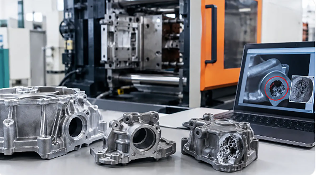
temperature changes. Die-cast parts and injection-molded components have
process variation that should be considered before CNC secondary operations are
specified.
For this reason, tolerances
should be selected with the material and manufacturing route in mind, not
copied from a previous drawing made for a different process.
Choose CNC Tolerances Around Mating
Conditions
Most functional tolerances arise where two parts meet.
The correct value depends on whether the relationship requires clearance, a
transition fit, or interference.
A clearance fit is used when
parts must assemble easily or move relative to one another. Examples include a
screw passing through a clearance hole, a sliding cover, or a shaft moving
inside a guide. The design must account for the maximum material condition of
both parts so the assembly cannot bind.
A transition fit is
appropriate when location is important but assembly should still be possible
without a heavy press operation. It is common for accurately located
components, hubs, and certain locating features.
An interference fit is used
when parts must remain fixed through friction, such as a pressed bushing,
bearing, or insert. Here, the tolerance stack must account for assembly force,
material behavior, wall thickness, surface finish, and temperature. An
interference value that works in a thick steel housing may crack a thin
aluminum wall or overstress a plastic component.
Whenever possible, specify fit
intent rather than choosing isolated limits without considering the mating
part. A hole tolerance only makes sense alongside the shaft, pin, insert, or
fastener it receives.
Consider the Entire Tolerance Stack
A part can meet every individual drawing dimension and
still fail to assemble. This happens when the accumulated variation across
several features exceeds the available clearance.
Review stack-ups for hole
patterns, enclosure interfaces, connector alignment, shafts, bearing seats,
cosmetic gaps, and assemblies that combine CNC components with molded, stamped,
or die-cast parts. Worst-case analysis is useful for safety-critical or
must-fit assemblies. Statistical analysis may be suitable when process
capability is established and production data supports it.
A common correction is not
simply tightening every contributing dimension. Often, the better solution is
to add clearance, use slots instead of fixed holes where adjustment is
acceptable, establish a single datum scheme, or redesign the locating method with
pins and clearance fasteners.
Use GD&T When Location and
Orientation Matter
Plus/minus dimensions are useful for straightforward
size control, but they do not always communicate how features relate to each
other. Geometric dimensioning and tolerancing, or GD&T, becomes valuable
when the part’s function depends on position, flatness, perpendicularity,
concentricity, profile, or runout.
For example, a hole may meet
its diameter tolerance but still be misplaced enough to prevent assembly. A
positional tolerance referenced to functional datums communicates the real
requirement more clearly. Similarly, a sealing surface may require flatness,
while a rotating shaft feature may need runout control relative to a datum
axis.
GD&T should be applied
deliberately. Over-specifying geometric controls creates the same cost problem
as excessive plus/minus tolerances. Select datum features that reflect how the
part is actually located during assembly and inspection. If the datum structure
does not match the functional assembly condition, measurement results can
become difficult to interpret and less useful.
Match the Drawing to the
Manufacturing Process
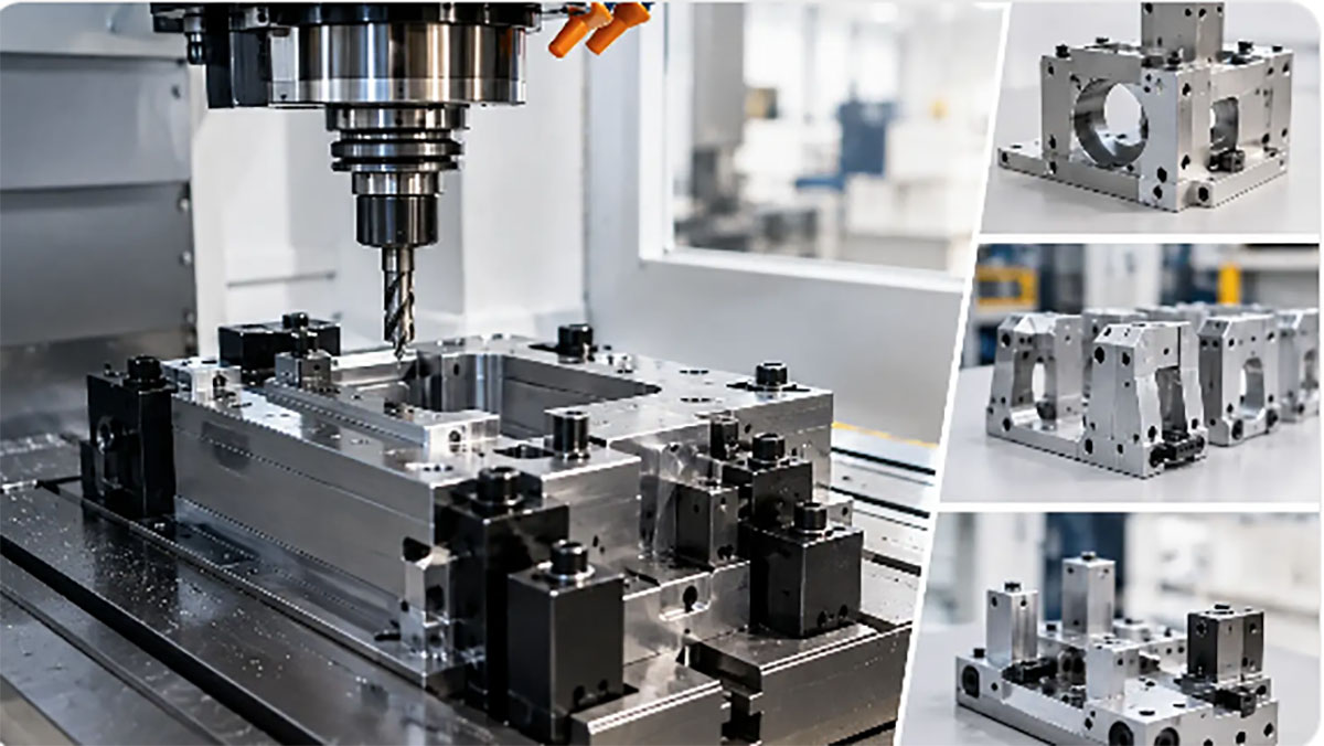
CNC machining is capable of high precision, but
capability depends on part geometry, machine access, fixturing, material condition,
feature depth, and the selected operation. A deep, small-diameter bore is more
difficult to control than a shallow accessible hole. A thin machined wall can
distort after unclamping. A tight profile across multiple setups introduces
greater alignment risk than a feature machined in one setup.
Before releasing a drawing,
ask practical process questions. Can the feature be machined with a standard
end mill, drill, reamer, or boring tool? Will the part need to be repositioned?
Is the tolerance required before or after anodizing, plating, painting, heat
treatment, or coating? Can the feature be measured reliably with available
gauges or a CMM?
Surface treatment deserves
specific attention. Anodizing and plating add material thickness. Heat
treatment can cause distortion. Bead blasting changes surface texture and can
soften sharp edges. If a precision bore, thread, or sealing face must remain
functional after finishing, state whether the dimension applies before or after
the treatment and coordinate any required masking or post-process machining.
Specify Surface Finish Separately
From Size Tolerance
Surface finish and dimensional tolerance are related
but not interchangeable. A shaft can be held to the right diameter while still
having a surface that is too rough for a dynamic seal. Conversely, a smooth
cosmetic face may not need a particularly tight dimensional tolerance.
Call out surface roughness
where it affects sliding wear, sealing, bearing performance, coating adhesion,
cosmetic appearance, or electrical contact. Avoid blanket finish requirements
across the entire part unless they are genuinely needed. A general finish
requirement can force unnecessary finishing operations on hidden or
nonfunctional surfaces.
Threads, tapped holes, and
counterbores also need practical consideration. Standard thread classes and
standard fastener clearances are usually more economical and easier to inspect
than custom limits. If thread engagement, pull-out strength, or insert
retention is critical, identify the material condition and the intended
assembly method early.
Build Inspection Into the Tolerance
Strategy
A tolerance that cannot be measured consistently is
not a useful production requirement. Define critical-to-quality features
clearly and align the inspection method with the risk. Calipers may be
sufficient for broad external dimensions, while precision bores, profile
controls, and complex feature locations may require pin gauges, bore gauges,
height gauges, go/no-go gauges, or coordinate measuring machines.
For initial samples and new
tooling, a first article inspection report can verify key
dimensions against the drawing. For ongoing production, inspection frequency
should reflect feature criticality, process stability, lot size, and the
consequences of a nonconforming part reaching assembly.
It is also useful to identify
which dimensions require inspection reporting and which only need to meet the
general drawing standard. Requiring full dimensional reports for every cosmetic
or low-risk feature can slow approval without improving product quality.
Review Tolerances Early With Your
Manufacturing Partner
The lowest-cost time to
resolve a tolerance issue is before material is cut. A manufacturability review can identify unnecessary
precision, inaccessible features, unrealistic datum schemes, thin-wall
distortion risks, coating conflicts, and stack-up problems while design changes
are still inexpensive.
For early prototypes, some
dimensions may be intentionally relaxed to validate form, ergonomics, or market
response before committing to production-grade requirements. For a functional
engineering prototype, critical interfaces should be controlled from the start.
The right approach depends on what the build is meant to prove.
Xiamen Creator Technology can
support this review across CNC prototypes, tooling, molded components,
secondary finishing, and assembled products, helping teams keep tolerance
decisions consistent as a product moves toward production.
A well-toleranced drawing
gives manufacturing teams a clear target without restricting the process
unnecessarily. Keep precision where it protects function, define how parts
locate and mate, and let noncritical features remain practical. That discipline
usually produces parts that cost less, inspect faster, and assemble with fewer
surprises.