Learn how to validate prototype designs through fit, function, material, user, and DFM testing before committing budget to production tooling at scale.

A
prototype can look correct on a screen and still fail the moment it meets a
mating part, a user’s hand, a production fixture, or a real load. The practical
question is not whether a prototype can be made. It is how to validate
prototype designs thoroughly enough that the next investment - tooling, pilot
production, or full assembly - is based on evidence rather than assumptions.
For product teams, validation
should reduce risk in a planned sequence. A cosmetic model, a functional
engineering sample, and a production-intent pilot all answer different
questions. Trying to answer every question with one prototype often wastes both
time and budget.
Define What the Prototype Must
Prove
Validation starts before selecting CNC machining, SLA,
SLS, silicone molding, or any other process. Define the decision that the
prototype must support. For example, an early enclosure model may need to
confirm size, appearance, button placement, and assembly access. A later sample
may need to prove snap-fit retention, drop resistance, heat performance, or
compatibility with internal electronics.
Turn the product requirements
into measurable acceptance criteria. “Feels strong” is not an acceptance
criterion. “The latch withstands 500 open-close cycles without cracking or
permanent deformation” is. “Fits the existing component” should become defined
dimensions, datums, allowable gaps, and assembly-force limits.
A useful validation plan
normally covers five areas: dimensional fit, functional performance, material
behavior, user interaction, and manufacturability. Not every project needs
equal depth in each area. A non-load-bearing cosmetic cover may require
extensive surface evaluation but limited mechanical testing. A safety-critical
clip or structural bracket requires the opposite approach.
Separate Must-Pass Requirements
From Preferences
Teams often lose time debating preferences alongside
critical requirements. Separate requirements into two groups. Must-pass
requirements include safety, regulatory constraints, key dimensions, load
capacity, sealing, electrical function, and compatibility with purchased
components. Preferences include surface texture, color options, branding
details, and secondary ergonomics.
This separation makes
prototype review more productive. If a sample misses a must-pass requirement,
the design needs action even if it looks polished. If it misses a preference,
the team can judge whether the improvement justifies another iteration.
How to Validate Prototype Designs
in Stages
The strongest validation programs move from low-cost
learning to higher-fidelity proof. Early prototypes should expose major errors
quickly. Later prototypes should focus on the details that affect tooling and
production consistency.
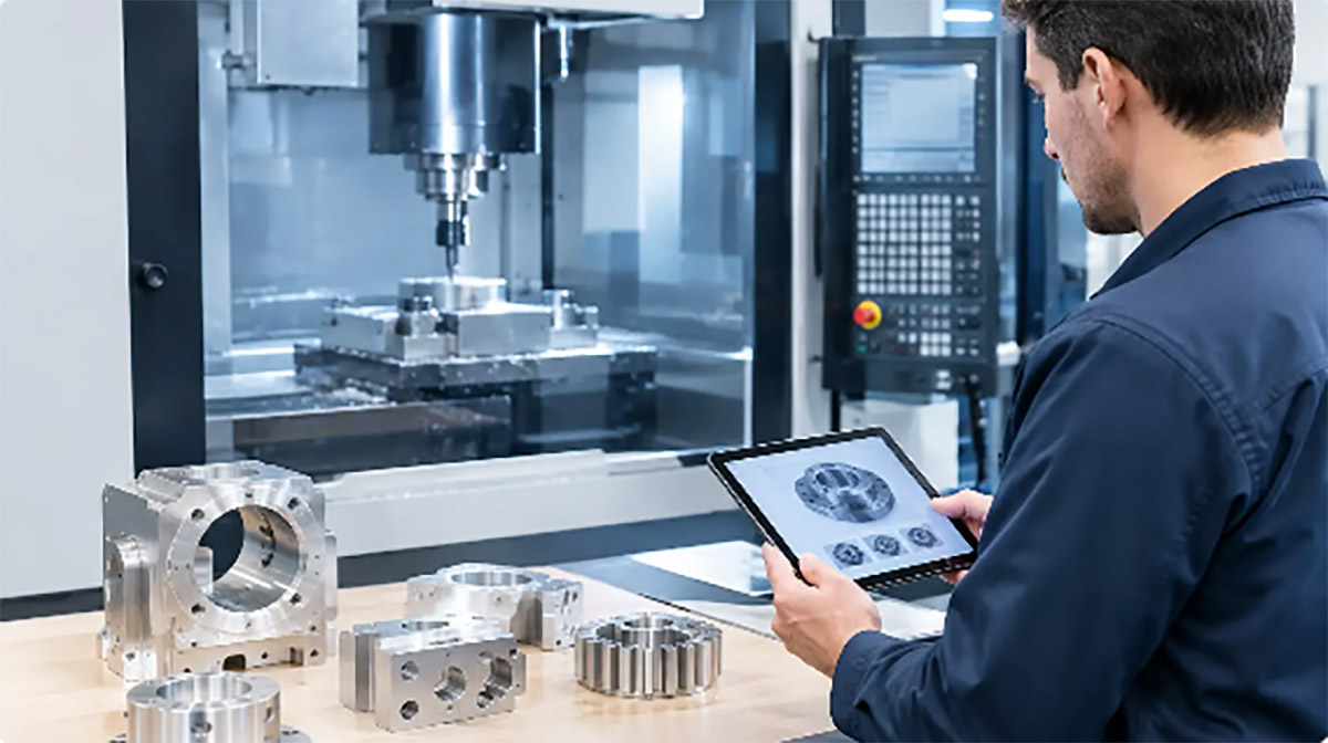
Start with form and fit. Check
overall dimensions, part interfaces, clearance around connectors, fastener
access, wall thickness transitions, and space for cables, batteries, seals, or
internal mechanisms. Use the actual mating parts whenever possible. Nominal CAD
dimensions are not enough when purchased parts have their own tolerances.
Next, validate function under
realistic conditions. A hinge should be cycled, a container should be filled, a
button should be pressed repeatedly, and an electronic enclosure should be
tested with the actual PCB and wiring installed. Test conditions should reflect
the product’s intended use rather than an ideal bench setup. If the product may
be dropped, exposed to heat, cleaned with chemicals, or assembled by operators,
include those conditions in the plan.
Then review appearance and
user interaction. This is especially relevant for consumer products, handheld
devices, controls, and visible housings. Confirm grip, reach, button feedback,
edge comfort, parting-line visibility, texture, and perceived quality. User
feedback is useful, but it should be structured. Ask users to complete defined
tasks and observe where they hesitate, apply excessive force, or misunderstand
the product.
Finally, evaluate whether the
design can be manufactured repeatedly. A single hand-finished prototype can
hide molding, machining, and assembly problems that will become costly at
volume. Production validation needs a different standard: not “can this sample
be made?” but “can this part be made consistently within tolerance, yield, and
cost targets?”
Choose the Prototype Process Based
on the Risk
Prototype process selection should follow the question
being tested. No method perfectly represents every production material or
process, so teams should avoid treating a single sample as final proof of every
requirement.
·
SLA printing is useful for high-detail visual models, complex geometry,
and early fit checks. Its resin properties may not represent an
injection-molded plastic part under impact, heat, or long-term stress.
·
SLS printing works well for functional nylon parts, clips, housings, and
assemblies where stronger, more durable prototypes are needed. Surface finish
and dimensional variation may require post-processing or allowance planning.
·
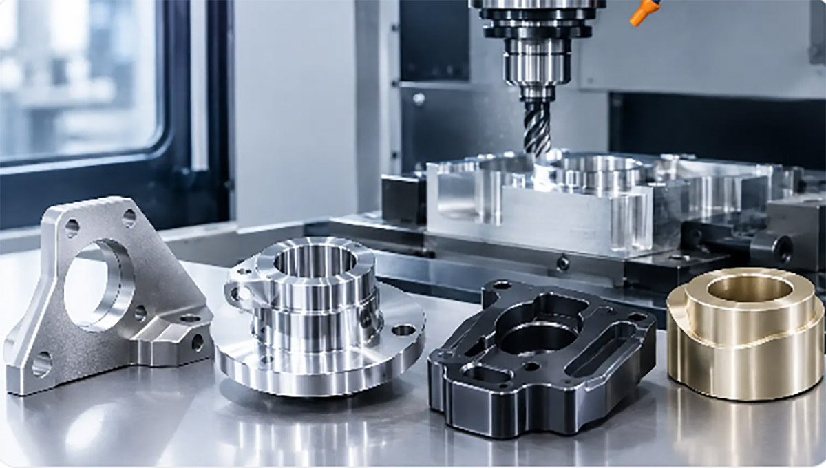
CNC
machining provides
accurate parts in engineering plastics and metals, making it suitable for
tolerance checks, structural testing, thermal applications, and parts that need
material properties closer to production intent.
·
Silicone tooling and low-volume molding can provide short runs for market
evaluation, assembly trials, and early production verification. It can also
reveal design concerns that a one-off printed sample will not show.
·
Prototype metal fabrication, stamping samples, or die-cast development
parts may be necessary when stiffness, conductivity, shielding, weight, or
surface durability are central requirements.
Material equivalency deserves
special attention. A prototype made in a substitute material can validate
geometry and assembly while remaining unsuitable for validating fatigue life,
chemical resistance, creep, or impact performance. Document what each prototype
does and does not prove. This prevents teams from carrying false confidence
into tooling.
Test Assemblies, Not Isolated Parts
Many prototype failures occur at interfaces. A housing
may meet its own dimensions but interfere with a connector. A gasket groove may
look correct but fail to compress evenly. A stamped bracket may fit the CAD
envelope yet be impossible to install after wiring is routed.
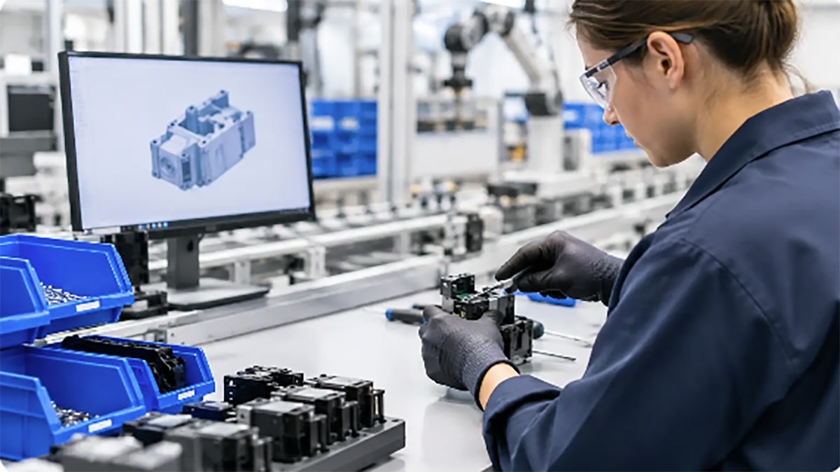
Build the relevant assembly as
early as possible. Include fasteners, adhesives, labels, wiring, purchased
components, and packaging inserts when they affect performance. Measure
stack-up across the full assembly, especially where multiple tolerances
accumulate. Use functional gauges or simple fixtures for repeated checks rather
than relying only on calipers and visual inspection.
Assembly trials should also
assess labor and sequence. Record how many steps are required, whether
orientation errors are possible, which features require excessive force, and
whether tools can reach every fastening point. These observations feed directly
into DFA, or design
for assembly. A part that functions well but requires slow, awkward assembly may
create avoidable cost at scale.
Validate for Manufacturing Before
Committing to Tooling
Tooling is where design
decisions become expensive to reverse. Before releasing a mold, die, or
production fixture, perform a DFM
review with
the intended manufacturing method in mind.
For injection-molded parts,
review draft angles, uniform wall thickness, ribs, bosses, gate locations, sink
risk, weld lines, undercuts, shrinkage allowance, ejection, and expected
cosmetic surfaces. For CNC parts, review tool access, internal radii, deep
pockets, thin walls, setup count, and tolerances that may drive machining time.
For sheet metal, check bend radii, bend relief, hole-to-bend spacing, material
direction, and hardware installation.
The right DFM change is not
always the one that produces the lowest piece price. Adding a feature or
adjusting geometry may modestly increase part cost while eliminating manual
rework, reducing scrap, or simplifying assembly. Evaluate the full commercial
effect across tooling, cycle time, yield, inspection, packaging, and labor.
A production partner should
also review inspection strategy at this point. Identify critical dimensions,
cosmetic standards, functional test methods, sampling levels, and reference
samples. Quality requirements that are not stated before production are
difficult to enforce afterward.
Convert Test Results Into Clear
Release Decisions
Prototype testing only creates value when results
drive decisions. After each build, document the sample revision, material,
process, inspection results, test conditions, failures, and corrective actions.
Photos and measurements are helpful, but the record should clearly state
whether each requirement passed, failed, or needs further evaluation.
Avoid making design changes
without assessing their downstream effect. Increasing a wall thickness may
improve strength but create sink marks in molding. Tightening a clearance may
improve perceived quality but reduce assembly yield. Changing a material may
solve impact performance while creating new warpage or finishing concerns. Each
revision should be reviewed across function, appearance, tooling, and cost.
For a final pre-tooling
review, confirm that critical risks have been tested with representative
materials and assemblies. If uncertainty remains, identify it explicitly and
decide whether it is acceptable, requires another prototype, or needs a
controlled pilot run. That discipline is often faster than rushing into tooling
and discovering the real problem after steel has been cut.
A prototype earns its value
when it answers a specific manufacturing or product question. Build each
iteration to remove the next highest risk, retain the evidence, and use those
findings to make the production release more predictable.