Learn how to improve assembly manufacturability with practical DFA choices that reduce labor, defects, lead time, and total production cost in volume.

A product can have well-designed
individual parts and still become expensive, slow, or unreliable to build. The
question of how to improve assembly manufacturability is
usually decided by small details: a screw that is hard to reach, two similar
components that can be mixed up, a cable that only fits after several manual
adjustments, or a tolerance stack that prevents a housing from closing
consistently. These issues may look minor in CAD, but they multiply across
pilot runs and production volume.
Assembly manufacturability is
the ability to put a product together repeatedly, efficiently, and correctly
using realistic production methods. It overlaps with design for assembly (DFA),
design for manufacturing (DFM), tooling design, component sourcing, and quality
planning. The objective is not simply to reduce the part count. It is to create
an assembly process with fewer decisions, fewer opportunities for error,
controlled variation, and predictable cycle time.
Start With the Actual Assembly
Sequence
Many assembly problems begin because the product is
evaluated as an exploded view rather than as a sequence of work. Review the
build from the first component placed in a fixture through final functional
testing and packaging. For every operation, ask what the operator must pick up,
orient, align, fasten, inspect, or test.
A useful process review
identifies the required tools, access direction, handling steps, and quality
checks for each station. If an operator must rotate the product repeatedly,
change tools several times, or hold one loose component while fastening another,
the process likely needs attention. The same is true when parts must be bent,
forced, trimmed, or adjusted to make them fit.
Build sequence also affects
serviceability and test strategy. A component that is easy to install early may
block access to a connector or prevent a later test. In some cases, changing
the installation order solves the problem. In others, the product design needs
a new opening, datum feature, or fastener location.
Early prototype
builds are
particularly valuable here. A prototype should not only confirm form and
function. It should be assembled as close as possible to the intended
production process, with assembly time, rework, and failure points recorded.
This provides better input than a design review based on models alone.
How to Improve Assembly
Manufacturability Through Part Reduction
Reducing part count is one of the most effective DFA
actions, but it should be done with engineering judgment. Each eliminated part
can remove purchasing activity, incoming inspection, storage, handling,
assembly labor, and a potential failure mode. A molded enclosure with
integrated locating tabs, for example, may replace separate brackets or
spacers.
However, combining parts can
create trade-offs. A more complex injection-molded part may need a more
expensive mold, longer molding cycle, side actions, or tighter process control.
A die-cast part may consolidate several stamped components but introduce different
surface-finish or tolerance constraints. The right decision depends on annual
volume, target cost, material requirements, tooling budget, and product life
cycle.
Review each component with
three questions: Does it perform more than one necessary function? Can its
function be integrated into an adjacent part? Does it require separate handling
only because the design lacks a locating or retention feature? The answers
often reveal opportunities to combine hardware, reduce brackets, integrate
hinges, use molded snap features, or simplify internal supports.
Standardize remaining
components wherever practical. Common screw sizes, thread types, washers,
connectors, and adhesive formats reduce purchasing complexity and prevent
operator mistakes. Standardization is especially valuable for OEM products that
share parts across several models.
Design Parts That Find Their Own
Position
An assembly should not depend on operator judgment for
basic alignment. Parts need clear datum surfaces and locating features that
guide them into the correct position before fastening, welding, bonding, or
testing.
Use features such as lead-ins,
chamfers, alignment pins, bosses, slots, ribs, and nesting surfaces to control
part location. A tapered lead-in can turn a difficult insertion into a
repeatable motion. A correctly designed pin-and-hole relationship can establish
position while allowing for normal molding or machining variation. For plastic
housings, use one round locator and one slot or oblong locator when thermal
expansion or tolerance variation must be accommodated. Two fully constrained
round pins can create interference if component dimensions shift.
Orientation is equally
important. Whenever possible, make incorrect assembly physically impossible. An
asymmetric geometry, keyed connector, offset hole pattern, or unique locating
feature provides mistake-proofing without adding inspection labor. If a part
can be installed backward and still appear to fit, it will eventually be
installed backward.
Avoid features that require
force to engage unless the force is controlled and verified. Press fits, snap
fits, and interference joints can be efficient, but they require careful
tolerance analysis, material selection, and process validation. A snap feature
that works in an SLA prototype may not behave the same way in production
injection-molded material.
Make Fastening Fast, Accessible,
and Repeatable
Fastener selection has a direct effect on cycle time
and quality. Minimize the number of fasteners, but also consider how each one
is installed. A screw placed deep inside a narrow cavity may be inexpensive on
a bill of materials yet costly in labor, tooling, and rework.
Where screws are necessary,
use a consistent type and head style. Provide adequate driver clearance,
straight-line access, and space for automated or torque-controlled tools.
Captive screws can prevent lost hardware. Self-tapping screws in plastic
require properly designed bosses and pilot holes to prevent cracking,
stripping, or inconsistent torque.
Alternative joining methods
may be appropriate when they simplify production. Ultrasonic welding, heat
staking, adhesive bonding, rivets, or snap fits can reduce hardware and shorten
assembly time. They also bring process constraints. Welding can complicate
repair, adhesives need surface preparation and cure control, and permanent
joints may limit disassembly for service or recycling. Select the method based
on product requirements, not only on unit assembly cost.
Control Tolerances Where They
Affect Fit and Function
Tight tolerances everywhere do not create a better
assembly. They usually raise tooling, machining, inspection, and scrap costs.
The goal is to apply tolerances intentionally at critical interfaces while
allowing reasonable manufacturing variation elsewhere.
Start with the dimensions that
control alignment, sealing, moving mechanisms, cosmetic gaps, and electrical
connections. Then examine the tolerance stack across all related parts. A
housing, gasket, printed circuit board, bracket, and connector may each be within
drawing limits while the completed assembly fails because their combined
variation exceeds available clearance.
Choose datum schemes that
reflect the way parts are actually located in assembly fixtures. For example, a
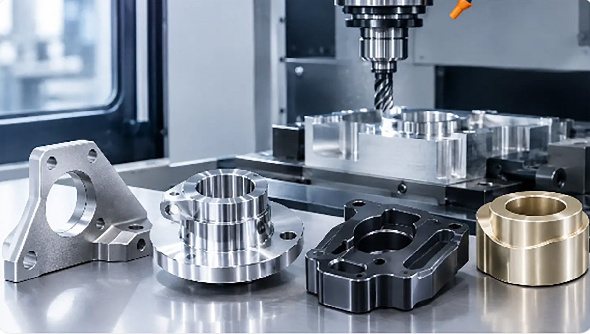
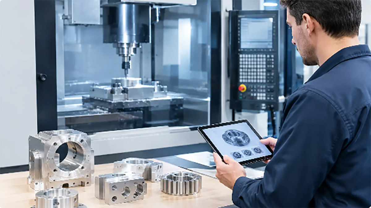
CNC-machined metal bracket should be dimensioned from the surfaces that locate
it in the final product, not from an arbitrary edge that has no assembly role.
For molded parts, account for material shrinkage, warp risk, gate location,
wall thickness, and mold-parting
requirements during the DFM review.
Functional gauges and go/no-go
fixtures are
often more useful than measuring every feature independently. They verify
whether the part fits and performs as intended at the assembly station. This
approach can improve inspection speed while focusing quality control on real
product risk.
Use Fixtures to Remove Variation,
Not Hide Design Problems
Assembly fixtures are essential when positioning,
force, angle, torque, or testing must be controlled. A basic fixture can hold
an enclosure in a repeatable orientation; a more advanced station can guide
insertion, verify component presence, control screw torque, and capture test
data.
Good fixtures reduce handling
and protect cosmetic surfaces. They should make the correct process easier than
an incorrect one. If an operator can load a part only one way, select the
required component, and complete the operation without repositioning the
product, consistency improves.
Fixtures should not become a
workaround for a design that is fundamentally difficult to build. If a highly
complex fixture is needed merely to hold unstable or poorly located parts
together, revisit the part geometry. The best solution may be a small design
change that removes a large amount of fixture complexity.
Validate With Pilot Builds and
Production Data
Assembly manufacturability cannot be fully proven
through CAD review. Run pilot builds using production-intent materials,
components, tools, and work instructions whenever possible. Record cycle time
by operation, first-pass yield, defect types, rework hours, torque results, and
test failures.
The most useful data is
specific. Instead of documenting that assembly is slow, identify that cable
routing adds 40 seconds, a latch fails to engage on 6% of units, or a cosmetic
scratch occurs during a particular insertion step. This supports focused
corrective action.
A practical pilot-build review
should examine at least four areas:
·
operator motion and accessibility at each station
·
component fit, orientation, and tolerance-related failures
·
fastening, bonding, or joining consistency
·
inspection and functional-test results
Update drawings, bills of
materials, fixtures, and work instructions together after changes are approved.
An engineering improvement that does not reach the production documentation can
create a new source of variation.
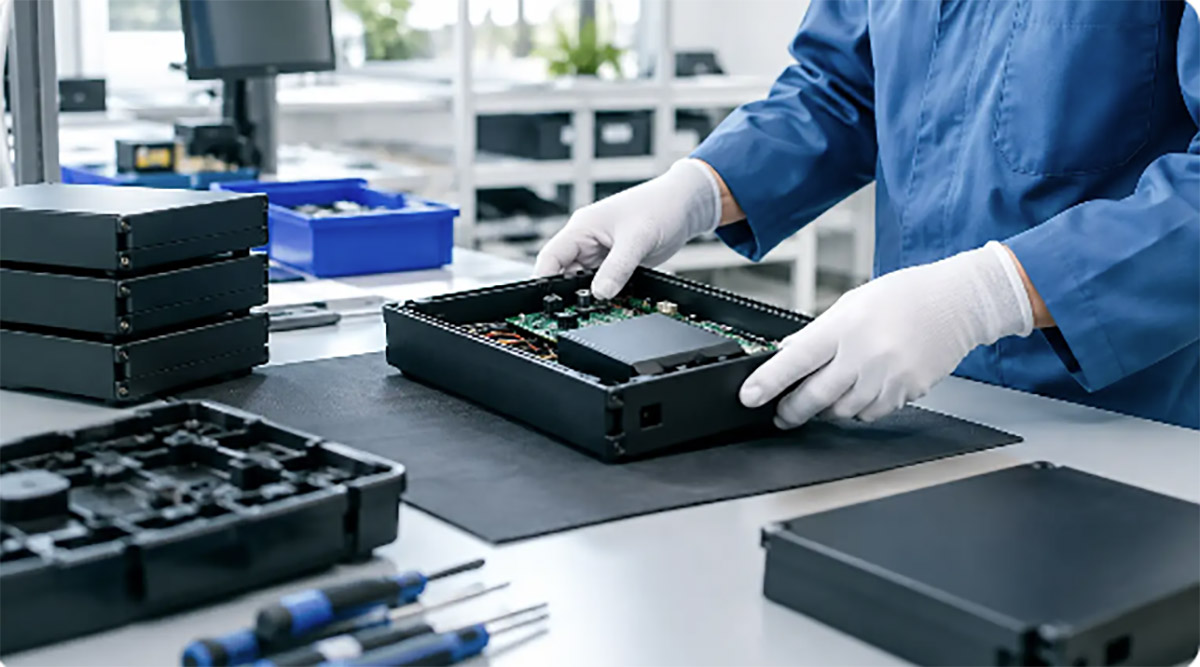
For products involving molded
plastic, silicone, metal parts, electronics, and final assembly, coordination
between suppliers matters as much as individual component quality. An
integrated manufacturing partner can review the interfaces among tooling,
fabricated parts, purchased components, and assembly operations before problems
reach mass production.
The most productive assembly improvements are usually not dramatic redesigns. They are deliberate decisions that make every unit easier to locate, join, inspect, and test. Treat each early build as evidence, then use that evidence to create a process that operators can repeat confidently at volume.