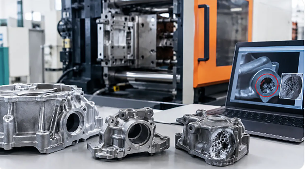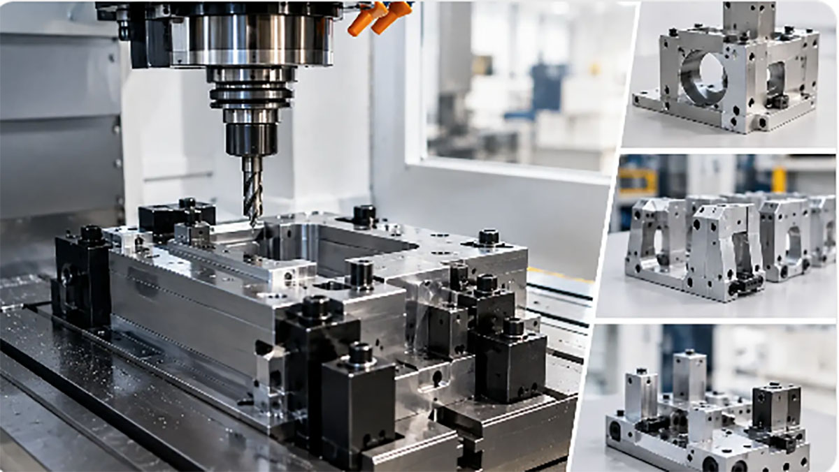
Metal stamping for custom parts delivers repeatable, cost-efficient production. Learn how design, tooling, materials, and volume shape the right process for buyers.
A
stamped metal component can look simple on a drawing and become expensive very
quickly in production. A small bend too close to a hole, an unrealistic
tolerance, or a late design revision can change the die approach, slow
qualification, and add avoidable cost. Metal stamping for custom parts is
highly effective when the part geometry, material, production volume, and
tooling strategy are aligned from the start.
For product companies and OEM
sourcing teams, the value is not just a lower piece price. Stamping can produce
consistent metal parts at speed while integrating operations such as blanking,
piercing, forming, embossing, and coining. The process is especially useful
when a design has moved beyond prototype quantities and requires repeatability
across pilot runs, ongoing production, or complete product assembly.
What Metal Stamping Is Designed to
Do
Metal stamping shapes sheet or strip metal with a
press and a dedicated tool, often called a die. Depending on the part, the
press may cut a flat profile, create holes and slots, form flanges, draw a
cup-shaped feature, or add local details in one or more operations. The result
is a part that is produced from controlled tooling rather than individually
machined from solid stock.
This distinction matters
commercially. CNC machining is often a practical
option for prototypes, low quantities, thick sections, and complex
three-dimensional geometry. Stamping becomes more attractive when a component
can be formed from sheet metal and the production volume can absorb the upfront
tooling investment. Once the die is validated, cycle times are short and
part-to-part consistency is easier to maintain.
Typical stamped components
include brackets, clips, terminals, shields, covers, spring elements, frames,
washers, latches, battery contacts, and appliance hardware. Some parts are
simple flat blanks. Others require multiple forming stages, tight feature
relationships, and secondary operations such as tapping, welding, plating, heat
treatment, or assembly.
When Metal Stamping for Custom
Parts Is the Right Process
The best candidates usually have relatively consistent
wall thickness because they begin as sheet or coil material. Their geometry
must also be compatible with press forming. Features that can be reached by
punches and forming tools are generally more efficient than deeply enclosed
shapes or highly sculpted surfaces.
Production volume is a central
decision point, but it is not the only one. A moderate-volume program may
justify tooling when the part replaces a more expensive machined or fabricated
assembly. High-volume programs normally gain the greatest benefit because
tooling cost is distributed across more units. For very low quantities, laser
cutting, bending, CNC machining, or a hybrid fabrication route may provide
better economics and faster design flexibility.
Material selection also drives
feasibility. Cold-rolled steel, stainless steel, aluminum, brass, copper,
phosphor bronze, and other spring-temper alloys can be stamped, but each
behaves differently under load. Stainless steel may provide corrosion
resistance but demand more from the tooling. Aluminum forms efficiently in many
applications but can crack at tight bends depending on alloy and temper. Copper
alloys are useful for electrical conductivity, while spring materials require
careful control of forming and post-form characteristics.
Part size, flatness, cosmetic
requirements, and tolerances need the same attention. Stamping can hold precise
dimensions, particularly where critical features are created in the same die
station. However, sheet metal naturally has variation from material properties,
springback, and forming stress. A specification should distinguish truly
functional tolerances from dimensions that do not need tight control. This
prevents a part from being over-tooled for requirements that add cost without
improving performance.
Tooling Choice Sets Cost, Speed,
and Flexibility
Tooling is the production system behind a stamped
component. The proper approach depends on annual volume, part complexity,
material, press capacity, and expected product changes.
A single-stage die performs
one operation per press cycle. It can be appropriate for simple blanks or
formed parts where lower output is acceptable. Transfer tooling moves a part
between separate stations and is often used for larger or more complex formed
components.
Progressive dies are widely
used for high-repeat production. Metal strip advances through a sequence of
stations, with each station completing a portion of the work. A finished part
exits after the final stage. This approach supports high output, stable feature
positioning, and reduced handling, but it requires more complex tool design and
a reliable strip layout.
Compound dies can perform
multiple cutting operations in one press stroke, making them useful for certain
flat parts. The right choice is not automatically the most automated die. If
design changes remain likely, a simpler tool or staged tooling plan may reduce
risk. If demand is proven and geometry is stable, a progressive die can deliver
a stronger long-term unit cost.
A capable manufacturing
partner should review the part before tool release. That review should cover
material specification, grain direction where relevant, burr direction, bend
radii, hole-to-edge spacing, forming sequence, expected springback, and
inspection requirements. It should also consider how the part will be handled
after stamping. A thin shield that stamps well may still deform during plating,
packing, or assembly if trays and process controls are not planned.
Design Details That Prevent
Production Problems
Many stamping issues begin
with a design that is technically possible but not production-friendly. Design for manufacturability is the practical process
of resolving those issues before money is committed to tooling.
Bend Geometry and Material Behavior
Tight bends can create cracking, especially with
harder tempers or materials that have limited elongation. As a working rule,
bend radius should be selected with the specific alloy and thickness in mind
rather than applied as a universal value. Bend relief may be needed where
flanges intersect to prevent tearing and distortion.
Springback must also be
designed into the tooling process. Metal tends to recover slightly after
forming, so the die may need to overbend the feature to achieve the finished
angle. This is normal, but it requires trials and measurement during tool
validation.
Holes, Slots, and Edge Conditions
Pierced features should generally remain far enough
from a formed edge to avoid distortion. Very small holes relative to material
thickness can be difficult to punch consistently and may reduce punch life.
Narrow webs between features can likewise create deformation or material
tearing.
Burr requirements need a clear
callout. Stamping creates a sheared edge with a rollover, burnished zone,
fracture zone, and burr. The acceptable burr height depends on the component's
function. Electrical contacts, hand-contact surfaces, precision assemblies, and
plated parts may need deburring or a controlled burr direction. A general note
to remove all burrs is often too vague for production control.
Tolerances and Inspection Strategy
Critical dimensions should be tied to how the part
functions in the assembly. For example, the distance between locating holes may
matter more than the outside profile of a bracket. Datum selection should
reflect how the component is fixtured, inspected, and assembled.
Inspection methods should be
defined early. Calipers may be sufficient for basic dimensions, while a
go/no-go gauge, optical measurement system, coordinate measuring machine, or
dedicated checking fixture may be needed for complex formed parts. The goal is
not to inspect every possible dimension with the most expensive method. It is
to verify the characteristics that protect fit, function, safety, and
appearance.
Stamping Often Needs Secondary
Operations
A finished custom part may involve more than the press
operation. Deburring, tumbling, tapping, riveting, spot welding, heat
treatment, plating, anodizing, powder coating, passivation, and laser marking
are common follow-on processes. Each one can affect tolerances, surface
condition, lead time, and cost.
Plating deserves particular
attention for contacts, corrosion-sensitive parts, and cosmetic products. The
base material, plating type, thickness range, adhesion requirements, and
masking areas should be established before production. If a part will be
welded, plated, or overmolded later, the stamped geometry should account for
fixturing and process access.
This is where integrated
manufacturing support reduces coordination risk. A stamped bracket may need a
plastic housing, fasteners, a silicone interface, and final assembly. Managing
the part as one component within the complete build helps ensure that
tolerances and finishes work together rather than being evaluated in isolation.
Xiamen Creator Technology can support this progression from design review and
prototype builds through tooling, stamped production, component sourcing, and
assembly.
A Better Way to Start a Custom
Stamping Program
A productive quotation package includes a current 2D
drawing with dimensions and tolerances, a 3D model when available, material and
finish requirements, expected annual quantity, and any critical functional or
cosmetic criteria. Photos of mating parts, sample components, or assembly
information can clarify requirements that drawings do not fully communicate.
Before approving a production
tool, plan for sample validation. First articles should confirm
dimensions, material condition, forming quality, burr condition, finish, and
assembly fit. For regulated or high-volume products, the approval process may
also include material certificates, inspection reports, control plans, gauge
studies, and retained samples.
The most cost-effective
stamped part is rarely the one with the lowest initial tool quote. It is the
part whose geometry, material, tooling, inspection, finishing, and assembly
requirements have been resolved early enough to support stable production. Give
the manufacturing team the functional intent behind the drawing, and they can
help turn a sheet-metal concept into a component that performs consistently
long after the first shipment.