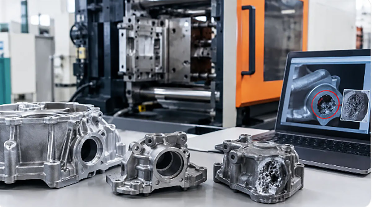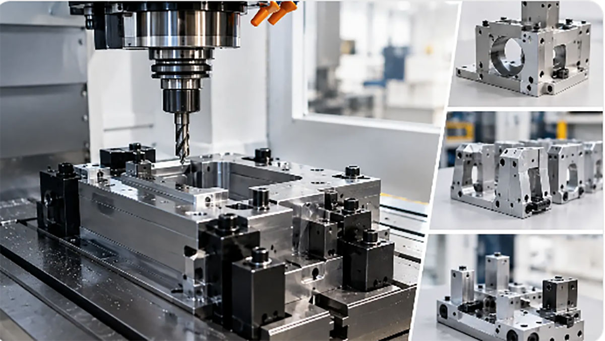
This guide to CNC machined prototypes covers material selection, tolerances, machining strategy, inspection, and the handoff to production for OEM teams.

A
prototype can look correct in a CAD assembly and still fail when it reaches the
bench. Threads may strip, a thin wall may chatter during machining, a mating
part may not seat, or the selected plastic may behave nothing like the intended
production resin. This guide to CNC machined prototypes focuses on the
decisions that make prototype parts useful for engineering validation, supplier
review, and the next production stage.
CNC machining is often
selected when a project needs functional parts with controlled dimensions,
production-relevant materials, and surface finishes that additive processes may
not provide. It is not automatically the lowest-cost option for every early
concept. Its value is highest when the prototype must answer a real technical
question: Will the assembly fit? Can the part carry load? Does the thread
design work? Can this geometry be machined repeatedly?
When CNC Machining Is the Right
Prototype Process
CNC machining removes material from a solid block or
bar using mills, lathes, drills, and other cutting tools. It works well for
metal parts, engineering plastics, precision fixtures, housings, brackets, heat
sinks, and components that need reliable mechanical performance.
Choose CNC machining when
material behavior matters. Aluminum prototypes can support stiffness, thermal,
and assembly testing. Stainless steel can validate strength and corrosion
requirements. Delrin, nylon, PC, ABS, and PEEK can provide a closer functional
comparison to molded plastic parts than many 3D-printed materials.
Machining is also appropriate
when the part needs features such as precision bores, flat sealing faces,
tapped holes, bearing seats, or tight mating interfaces. These features can be
produced accurately, but they should be specified according to function rather
than assigned tight tolerances by default.
For visual form studies,
ergonomic models, or highly organic shapes, SLA
or SLS may
be faster and more economical. For a molded plastic part that needs a small
pilot run, soft tooling or prototype injection molding may be the better next
step. The correct process depends on what the prototype needs to prove.
Start With the Question the
Prototype Must Answer
Before sending files for quotation, define the
validation purpose. A functional prototype, a fit-check sample, a cosmetic
model, and a production-intent first article have different requirements.
Combining all four into one request often adds cost and lead time without
improving the decision the team needs to make.
A fit-check part may only require
critical external dimensions, hole locations, and interface features. A
functional test part may require the final material grade, controlled wall
thickness, and actual fasteners. A cosmetic sample may require bead blasting,
anodizing, painting, or polished surfaces, even if some internal dimensions can
remain less controlled.
For each part, identify the
critical-to-function features: mating surfaces, datum faces, hole patterns,
threads, sealing interfaces, and moving clearances. This gives the machining
team a practical basis for tolerance review and inspection planning.
Prepare Files That Support Fast,
Accurate Quotation
A clean 3D CAD model is the
foundation, but it is not enough for every project. Provide a neutral STEP
or IGES file alongside the native model when available. For dimension-critical
components, include a 2D drawing with revision level, units, materials, finish
requirements, tolerances, and inspection notes.
The drawing should establish a
sensible datum scheme. A datum is not simply a convenient edge to measure from.
It should reflect how the part is located in an assembly or fixture.
Well-chosen datums reduce ambiguity when a supplier programs machining
operations and when quality personnel inspect the finished part.
State the material clearly,
including alloy or grade where relevant. “Aluminum” can mean 6061-T6, 7075,
5052, or another grade with different strength, corrosion behavior,
machinability, and cost. Similarly, nylon may require clarification on filled
versus unfilled material, color, and moisture-related requirements.
If no formal drawing exists,
communicate what matters in writing. Specify the interfaces that must fit, the
features that must be inspected, and the surfaces that are cosmetic. This is
much more useful than applying a blanket tight tolerance to the entire model.
Design for the Limits of Cutting
Tools
A CNC machine cannot create every CAD feature exactly
as modeled. Internal corners retain a radius because round cutting tools cannot
produce perfectly sharp inside corners. If a square component must sit in an
internal pocket, add corner reliefs or specify a radius compatible with the
mating part.
Deep, narrow pockets increase
machining time and can reduce accuracy because longer tools are more prone to
deflection and vibration. A practical approach is to avoid excessive
depth-to-width ratios where the geometry allows it. If a deep feature is
essential, discuss whether it can be machined from two sides, split into
separate components, or produced with a different process.
Thin walls need particular
attention. Metal walls can flex under cutting forces, while plastic walls may
warp as internal stress is released during machining. There is no universal
minimum wall thickness because material, wall height, geometry, and finish all
affect the result. Identify thin sections early so the manufacturing team can
recommend fixturing, machining sequence, or design changes.
Threads should match the
intended fastener system and material. Threaded holes in aluminum are common,
but repeated assembly or high pullout loads may call for threaded inserts.
Small threads and deep threads are possible within limits, yet they require
suitable tool access and careful depth specification.
Tolerances: Apply Control Where It
Creates Value
Tighter tolerances increase cycle time, inspection
effort, scrap risk, and cost. They are justified for critical fits, locating
features, bearing bores, sealing surfaces, and precision mechanisms. They are
rarely necessary on every nonfunctional face.
A general machining tolerance
can control noncritical dimensions, while specific tolerances are assigned to
functional features. Geometric dimensioning and tolerancing can be useful for
complex relationships such as true position, flatness, perpendicularity, and
profile. However, it should be used only when the design team understands the
inspection method and functional need behind the callout.
Consider the full tolerance
stack, not only individual part dimensions. A housing, gasket, fastener, cover,
and PCB may each be within specification while the assembled product still
binds or leaks. Prototype builds are the right time to measure actual stacks
and adjust the design before tooling investment.
Material and Finish Decisions
Affect More Than Appearance
Material selection should reflect the test objective.
Aluminum 6061-T6 is commonly used for housings, brackets, and general
functional prototypes because it machines efficiently and accepts several
finishes. Aluminum 7075 offers higher strength but may not be necessary for
standard structural parts. Stainless steel provides durability and corrosion
resistance, though machining time and cost are usually higher.
For plastics, Delrin is
suitable for low-friction components and precision machined parts.
Polycarbonate offers impact resistance and transparency options. ABS can
support many enclosure and fixture applications, while PEEK is reserved for
higher-temperature or chemically demanding uses where its cost is justified.
Finishes can change dimensions
and performance. Anodizing improves aluminum corrosion resistance and
appearance, but coating buildup matters on close-fitting features and threads.
Bead blasting creates a uniform matte texture but can soften fine cosmetic
details. Powder coating and painting add more thickness than many conversion
coatings. Call out masked areas or post-finish machining requirements when fit
surfaces must remain controlled.
Plan Inspection Before the Parts
Are Made
Inspection should match risk. A simple bracket may
need dimensional verification of hole locations and key overall dimensions. A
precision assembly part may require a first article inspection report,
calibrated measurement equipment, and documented results for every critical
characteristic.
Communicate measurement
expectations during quotation, not after production starts. If a bore requires
a plug gauge, if flatness needs a surface plate check, or if color must be
approved against a physical standard, those details affect process planning.
For assemblies, request a
trial build when possible. Individual components can pass inspection yet reveal
interference, cosmetic gaps, incorrect fastener engagement, or cable-routing
issues only after assembly. This is particularly valuable for electronics
housings, consumer products, and multi-process builds involving machined,
molded, stamped, and sourced components.
Use Prototype Results to Improve
the Production Path
A CNC prototype is not just a part to test. It is
manufacturing feedback in physical form. Record where assembly takes too long,
where operators need special handling, where fasteners cross-thread, and where
a cosmetic surface is vulnerable to damage. These observations inform DFM and
DFA changes before production tooling is committed.
Some prototype geometries are
appropriate for machining but expensive or impractical
for molding. Others may be easy to mold but need draft angles, uniform walls, ribs,
and revised undercuts. Discuss the expected production process early so that
prototype decisions do not create avoidable redesign work later.
When a product uses multiple
processes, coordinated manufacturing support can reduce handoff delays. Xiamen
Creator Technology can align machining, prototype tooling, molding, finishing,
component sourcing, and assembly requirements around the same approved design
data and quality checkpoints.
The most effective prototype
order is not the one with the most exacting specification. It is the one that
produces dependable evidence for the next decision, whether that decision is a
design revision, a pilot build, or release to production.